These directions will likely be easy to grasp and apply. 4 way trailer connectors are typically used on small trailers such as boat snowmobile utility and other trailers that that do not use brakes.
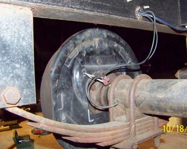
Trailer Connector Pigtail Replacement Amp General Trailer
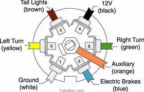
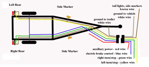
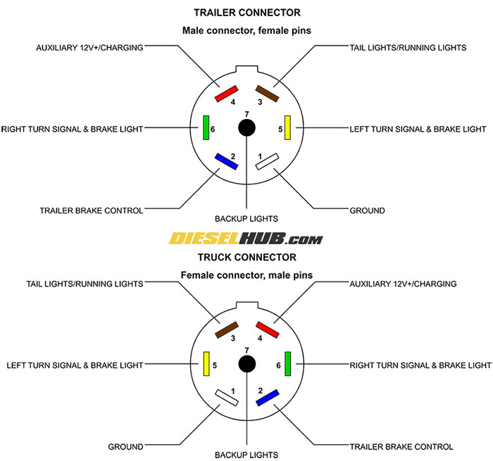
Trailer with brakes wiring diagram. 2 axle trailer brake wiring diagram whats wiring diagram. It reveals the parts of the circuit as streamlined forms as well as the power and signal connections in between the gadgets. First knowing the diagram of cables for trailer will be helpful during troubleshooting. A wiring diagram is a streamlined conventional pictorial representation of an electric circuit. The four wires control the turn signals brake lights and taillights or running lights. 7 pin trailer wiring diagram with brakes amazing 7 wire trailer 7 pin trailer wiring diagram with brakes.
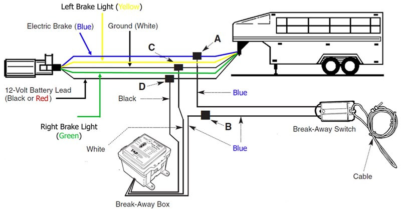
Wiring diagram comes with a number of easy to adhere to wiring diagram instructions. It really is supposed to assist all of the typical person in developing a correct program. Sometimes the cables will cross. The 5th pin a blue wire gives power to operate or disable the trailer brakes. Injunction of two wires is usually indicated by black dot on the junction of 2 lines. They also provide a wire for a ground connection.
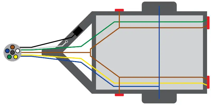
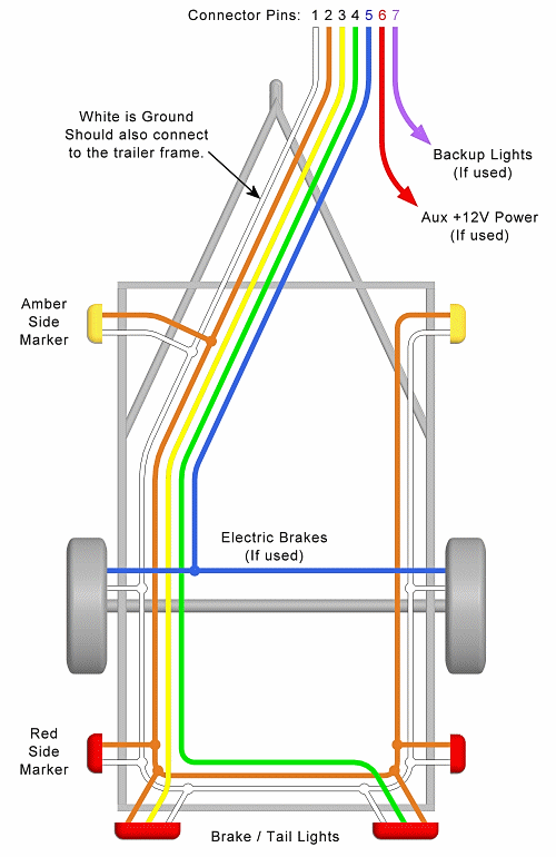
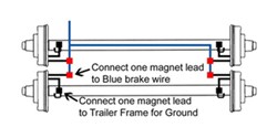
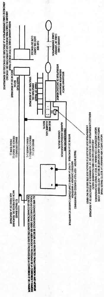
Trailer wiring diagram with electric brakes 7 pin trailer wiring diagram with electric brakes 7 way trailer plug wiring diagram with electric brakes trailer light wiring diagram with electric brakes every electric arrangement is composed of various distinct pieces. As the name implies they use four wires to carry out the vital lighting functions. 1 4 wire the first 4 pins white brown yellow green just like the 4 pin connector above. Trailer brake breakaway wiring diagram wiring library trailer breakaway wiring diagram by bismillah. Symbols that represent the ingredients inside the circuit and lines that. Trailer wiring diagrams trailer wiring connectors.
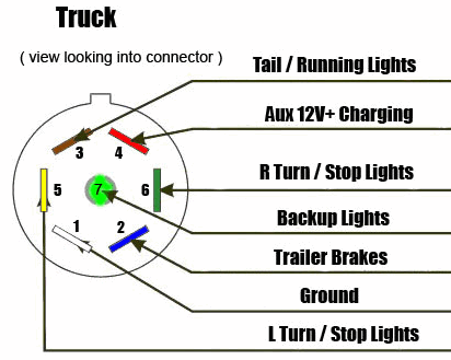
It helps immediately in fixing errors. Trailer wiring diagrams trailer wiring connectors various connectors are available from four to seven pins that allow for the transfer of power for the lighting as well as auxiliary functions such as an electric trailer brake controller backup lights or a 12v power supply for a winch or interior trailer lights. Various connectors are available from four to seven pins that allow for the transfer of power for the lighting as well as auxiliary functions such as an electric trailer brake controller backup lights or a 12v power supply for a winch or interior trailer lights. A wiring diagram is a kind of schematic which uses abstract pictorial symbols showing every one of the interconnections of components in a very system. When issues occur using the trailer motorist might want to know where the problem place is located. If a trailer has brakes then it needs a connector with at least 5 pins.
Wiring diagrams are made up of a couple of things. But it doesnt mean link between the cables. Traditional trailer with brakes use a 5 pin connector. Assortment of electric trailer brake wiring schematic. 4 way trailer connectors are. There will be primary lines which are represented by l1 l2 l3 and so on.
Each component should be set and connected with different parts in specific way. As stated earlier the lines in a 7 pin trailer wiring diagram with brakes signifies wires.
Gallery of Trailer With Brakes Wiring Diagram