Electric brake controller wiring diagram. Speed controller for ezip and izip electric bicycles speed controller for ezip coastline and trailz plus izip mountain trails trailz skyline and urban cruiser electric bicycles.

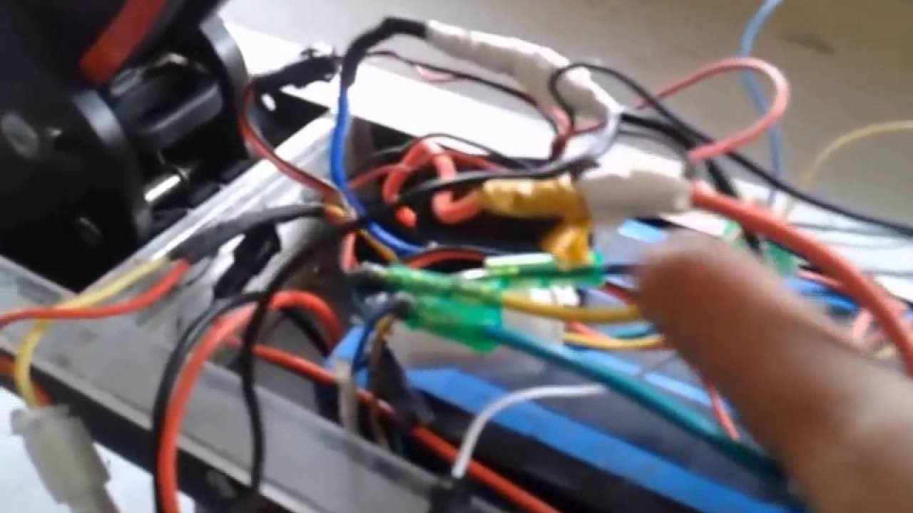
Speed Controller Hacked On Razor E300 Scooter Episode 4
Tre2401 controller wiring diagram. Wiring diagrams show components mounted in their general location with connecting wires. Typical controller markings typical elementary diagram table 4 control and power connections for across the line starters 600 v or less from nema standard ics 2 321a60. If its a 24 volt tr2421 controller you need then this is the control module for you. Zinc pulse razor etc see photos for details on plugs included on this module as there are different configurations. And it replaces the l controller model tre1201 made by hangzhou hebao power co ltd. A wiring diagram is used to represent how the circuit generally appears.
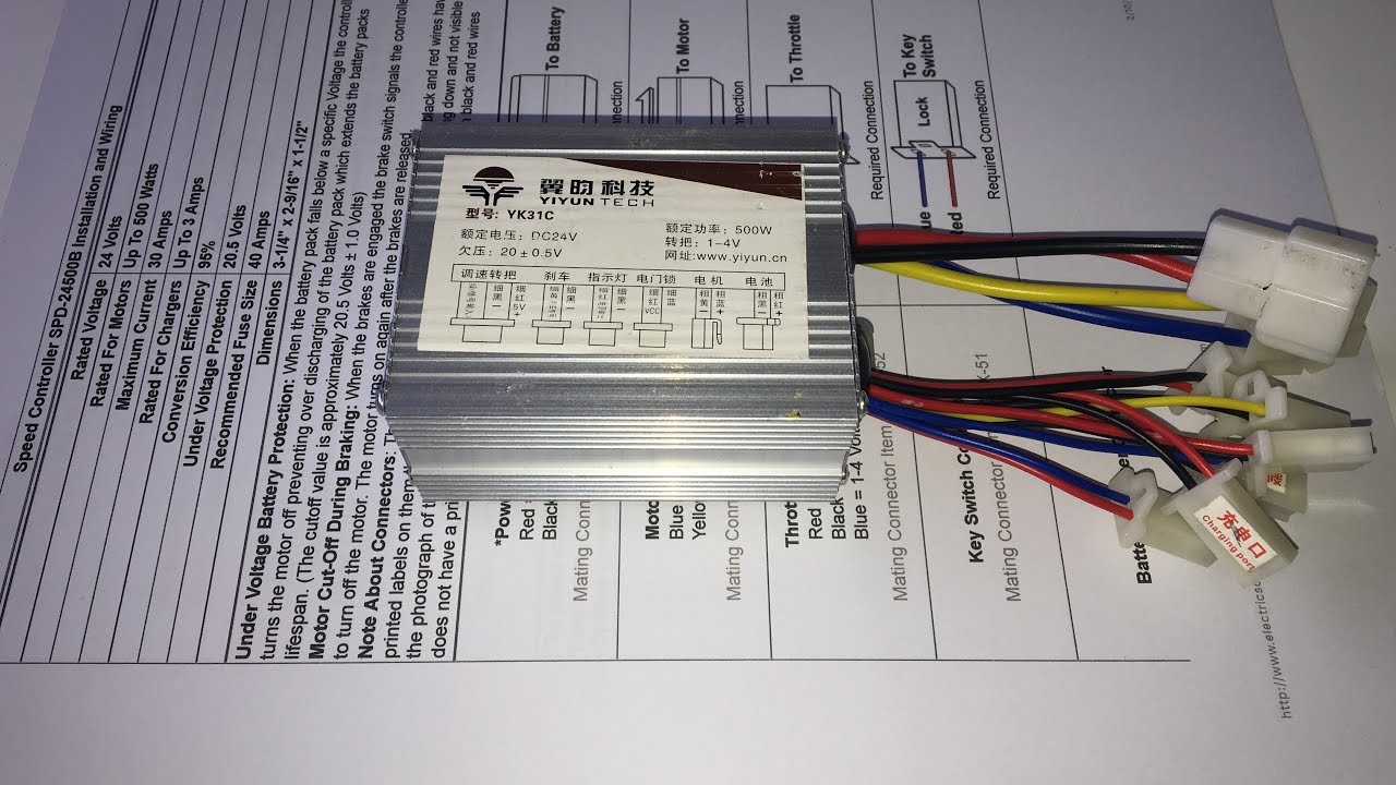
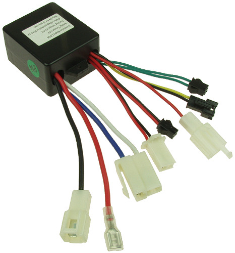
Electric scooter controller module model lbd8 tre2401 pulse reverb p100 1995. Its just a matter of wiring a few parts and components together to the speed controller. Brand new speed controllercontrol module to suit various model electric scooters. This is a 12 volt controller with model number lbd8 1 manufactured by yiyun tech. Wiring diagram book a1 15 b1 b2 16 18 b3 a2 b1 b3 15 supply voltage 16 18 l m h 2 levels b2 l1 f u 1 460 v f u 2 l2 l3 gnd h1 h3 h2 h4 f u 3 x1a f u 4 f u 5 x2a r power on. Variety of e bike controller wiring diagram.
A wiring diagram is a streamlined standard photographic depiction of an electric circuit. Model 24v 35a cte 2435 002 and cb24 yr8. It reveals the elements of the circuit as streamlined shapes as well as the power and signal links in between the gadgets. To be sure if this hangzhou hebao tr2421 pulse sonic or pulse sonic xl controller is the controller you need simply check the label on your old controller for the controller model number and voltage. Wiring an electric scooter bike or go kart is as simple as it looks in the drawing. Break away systems may be added to the service brake circuit.
This replacement controller for the pulse rk9 or revster scooter is just the part that you need. This controller is for bikes that have two brake switch connectors one connector for each brake lever switch cable. Auxiliary connection is optional it may be connected to any 12v to 24v constant power source or left unconnected. Elecbrakes is designed to operate 1 to 2 braked axles. To help illustrate the differences between wiring diagrams and schematics a basic control circuit will first be explained as a schematic and then shown as a wiring diagram. The speed controllers wiring directions will precisely indicate which wires to connect to which parts and components.
Gallery of Tre2401 Controller Wiring Diagram