It covers both single stage. One furnace is the main furnace and the other furnace is the secondary furnace.
Classified Facts On York Furnace Parts Only The Experts Know
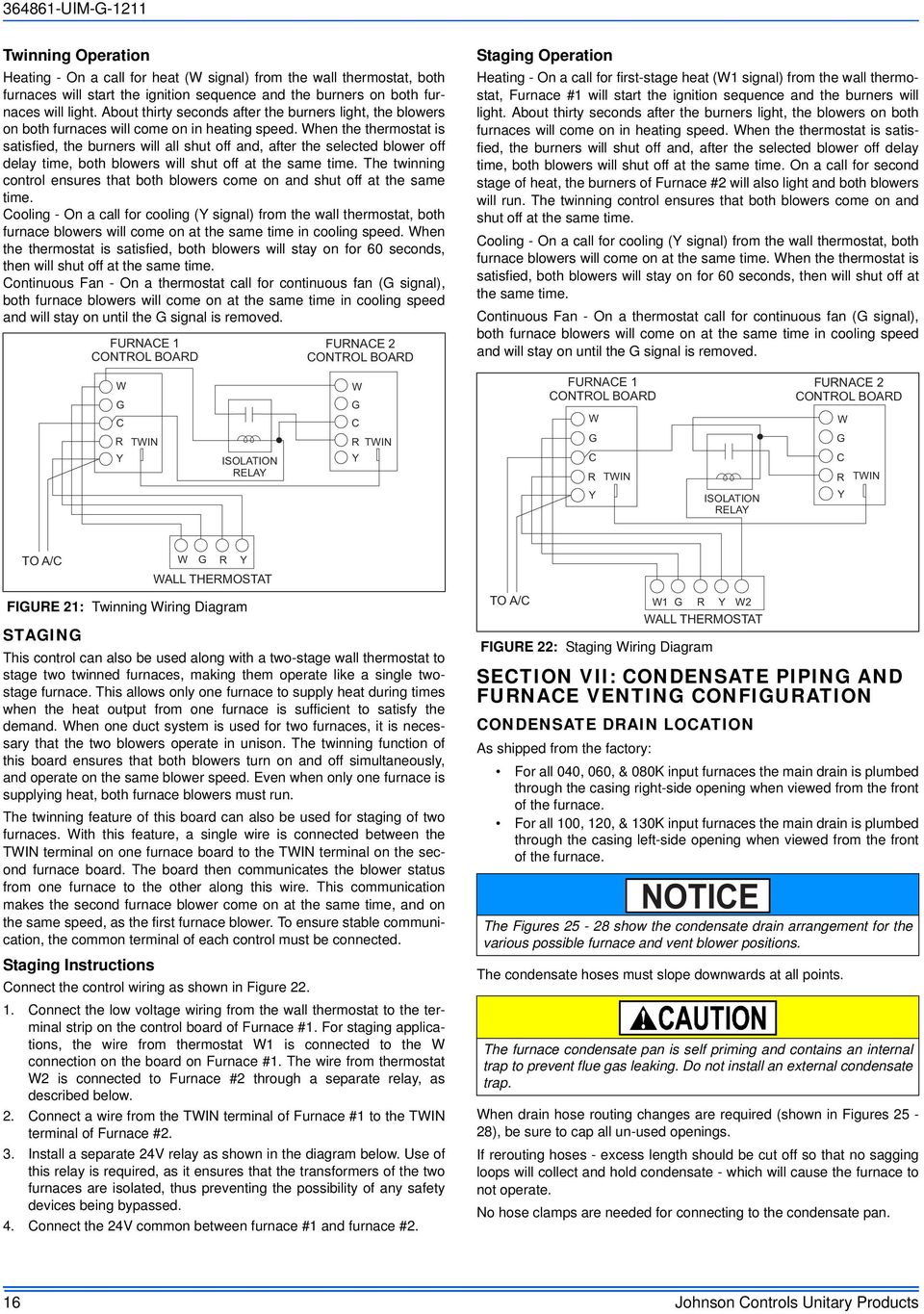
Twinning furnace wiring diagram. The cable can be cut to a convenient. Variety of gas furnace wiring diagram pdf. Page 23 figure 18 ut electronic controls 1028 928 control board twinning connection single stage operation a099201. Route the three wire cable along the same path as the thermostat wiring to the twinning control. Quantity sealing tape 2 external extension harness 327962 701 1 main twinning harness 327957 701 1 secondary twinning harness 327959 701 1 two stage furnace wiring diagram 327891 101 1 single stage furnace heat wiring diagram 327893 101 1 single stage furnacetwo stage heat wiring diagram 327892 101 1 label 327956 101 1. Table 1 models fg9mxt fg9mxe n9mse n9msb 0601714 0601714 0601410 0601410 0801716 0801716 0601714 0601714.
All control wiring must be connected as. It reveals the parts of the circuit as streamlined forms and the power and signal links between the devices. Connect the three wires to the corresponding fanled sensor in puts on the furnace 1 section of the twinning control. The twinning control uses all low voltage wiring between both furnaces and the room thermostat. A wiring diagram is a simplified standard pictorial representation of an electric circuit. The main furnace controls the operation of the secondary furnace.
4 table 1 kit contents description part no. Furnaces it is necessary to use a fieldsupplied 24vac pilotduty relay and a fieldsupplied 24vac115vac transformer as shown in the individual wiring diagrams to prevent overloading furnace 24vac115vac transformer. This is a very simplified version of furnace twinning but it should give you he basics to assure proper operation. It shows the parts of the circuit as simplified shapes and the power and also signal links between the gadgets. Attach to the 1 furnace control mounting plate next to the furnace control module. Connect the room thermostat to the twin ning control.
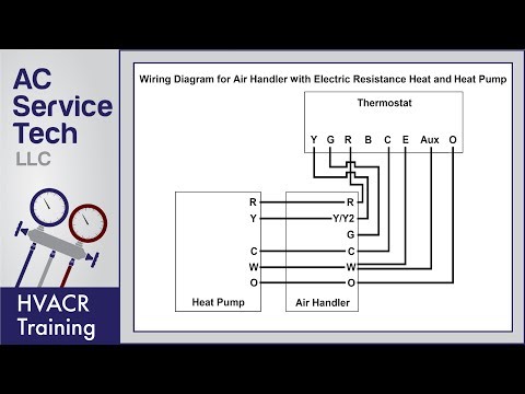
Standard ac with standard furnace control wiring standard furnace standard thermostat standard ac condenser 1st stage heat white 24 volt fan only operation common air conditioning ac contactor control board 1 this diagram is to be used as reference for the low voltage control wiring of your heating and ac system. Use adequate wire size for all control circuit loads just as you would with any thermostat 18 awg minimum. Assortment of goodman furnace wiring schematic. All control connections are made to the main furnace and main furnace wiring harness. Connect the twinning control to each furnace. Twinned furnaces in these instructions are also referred to as the left hand furnace lh and right hand furnace.
A wiring diagram is a streamlined standard pictorial depiction of an electric circuit.
Gallery of Twinning Furnace Wiring Diagram