Collection of ul 924 relay wiring diagram. The load control relay needs to have provision for connection to both the normal and emergency branch circuits as permitted by nec 7009b3.
Ul 924 Relay Wiring Diagram
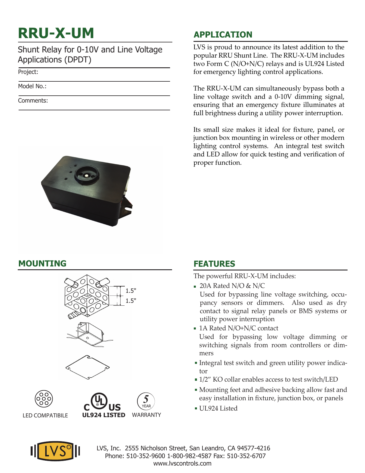
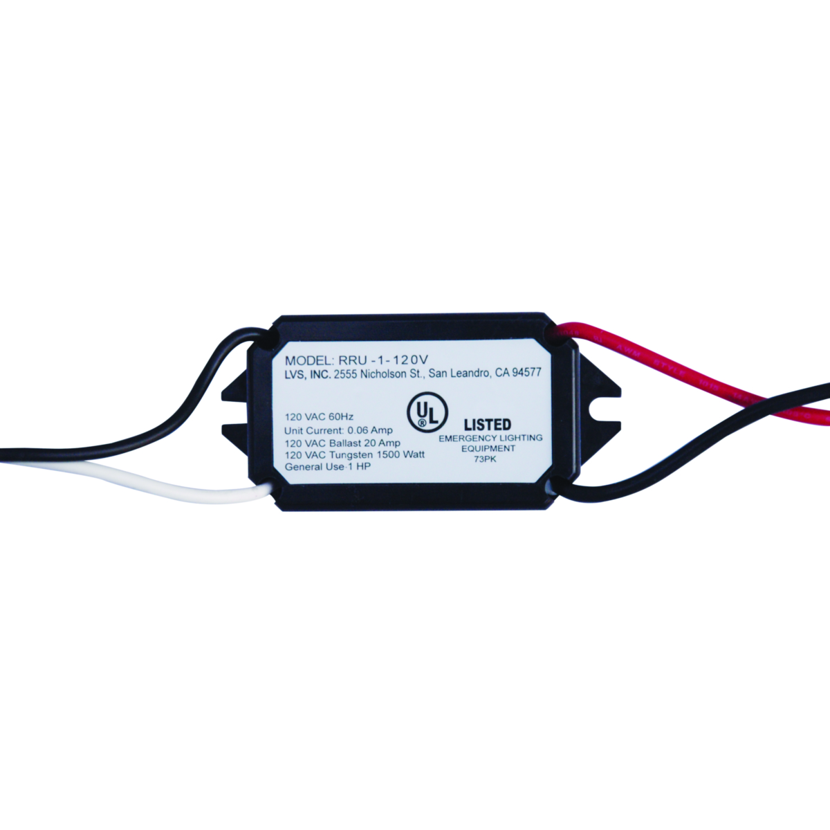
Ul 924 relay wiring diagram. Typical wiring diagrams emergency lighting wiring diagrams when using a central inverter. It shows the elements of the circuit as streamlined forms and the power and signal connections in between the devices. Red led should illuminate. Turn off normal power transfer power and wall switch. A wiring diagram is a streamlined standard pictorial representation of an electric circuit. Relay interface module rim 37 ul 924 remote relay unit rru.
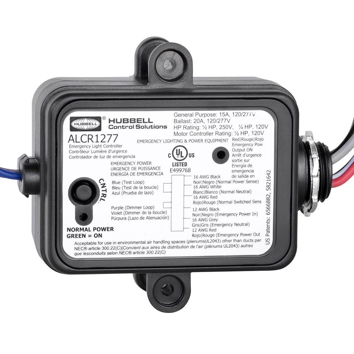
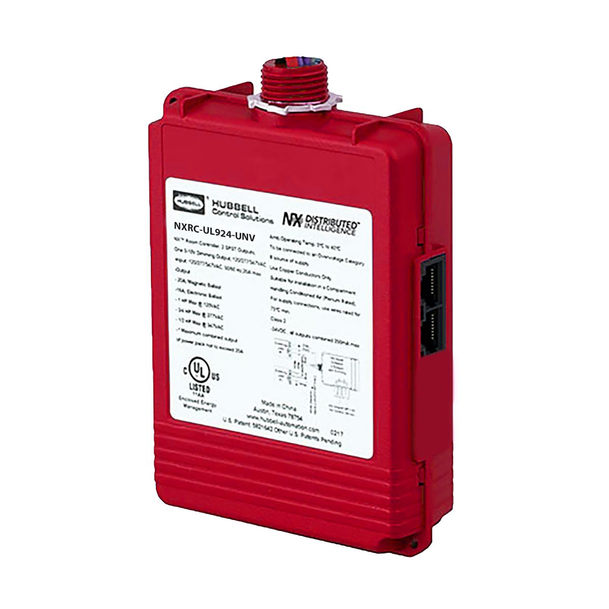
Relay contact rated for 277v50a minimizes power losses and provides. Occupancy and vacancy sensors. Outdoor lighting wall mount. Our enclosed 20 amp electrically held ul 924 automatic load control relay is specifically designed for projects requiring control of an emergency lighting along with controlled general lighting in a space. Esr relays with a single transmitter typical transmission distance. Our emergency lighting automatic load control relays are.
Parking garage canopy. In automatic load control applications when normal power is present the esr relay coil is activated and the emergency panel is fed from normal power. Our ul924 emergency lighting relays can be used for automatic load control or bypassshunt applications to turn on emergency lighting in the event of the loss of normal utility power. Wiring diagrams lx and cx panels power packs and wihubb smart packs the hubbell building automation ul 924 enclosed bypass relay with remote emergency control can be connected to various hubbell building automation control systems and devices as indicated in the following wiring diagrams. Such a switch was really necessary for dimmer branch circuits especially since or a simpler ul load control relay to energize an emergency lighting circuit. Ul automatic load control relay wire relay according to wiring diagram.
Up to 50 feet indoors for use with models with rf suffix initial wiring verification 1. The lighting on the emergency circuit is switched on and. Wire relay according to wiring diagram. Upon loss of normal power the ul 1008 listed transfer switch shifts the load over to the emergency source and the load control relay concurrently overrides any dimmer settings as noted above. Tenial ata septemer 218 rru ul 924 remote relay unit aton 112 igwa out peactree city 2 0 wwweatoncomligting for service or tecnical assistance 1 800 553 3879 21 aton ll rigts reserved printed in a pulication o d60en eptemer 218 peciications and. Ul listed to ul 924 standard for life safety emergency lighting and power equipment.
Modular wiring system with dali control components.
Gallery of Ul 924 Relay Wiring Diagram