16mm pigtail wire connector socket plug for u16f1 u16f2 push button switch. Last connect a wire between the 10k ohm and ground to arduino pin number two.

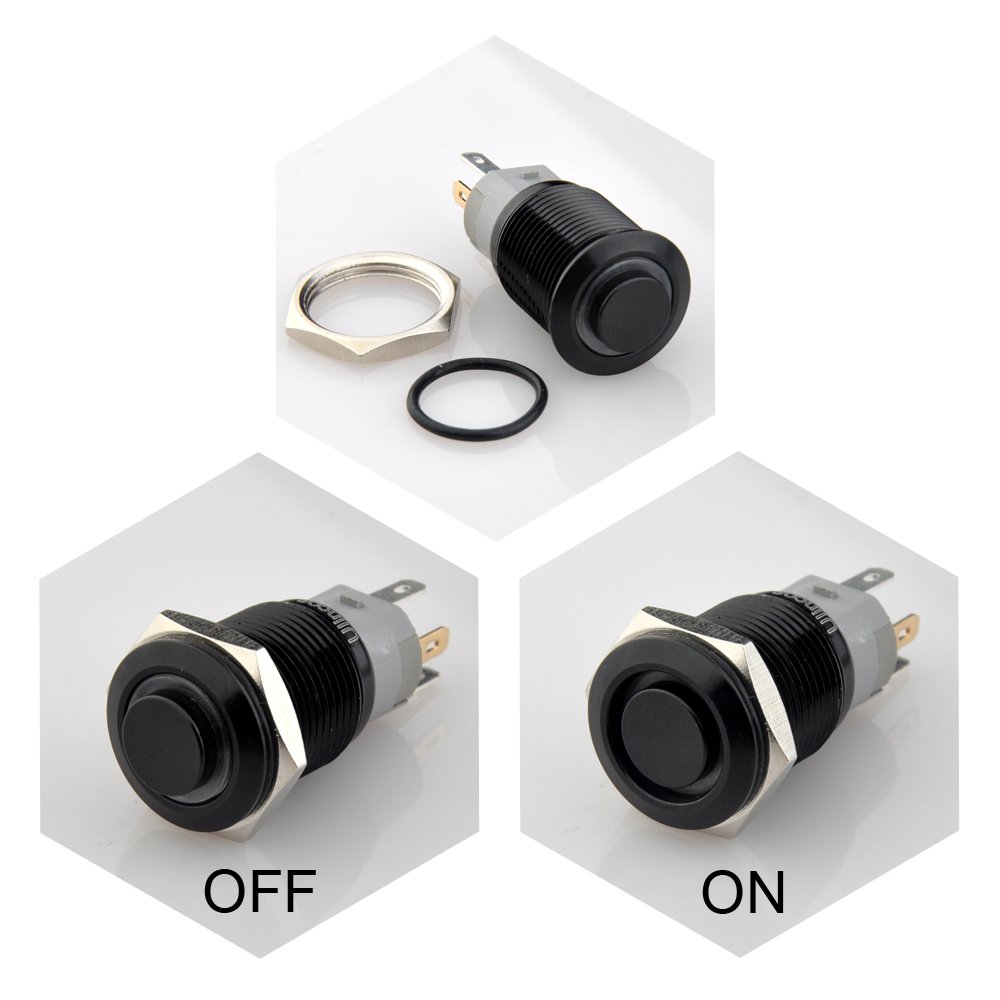
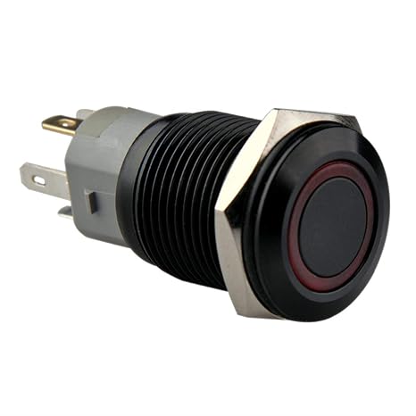
Ulincos Latching Pushbutton Switch U22a4 1no1nc Spdt On Off
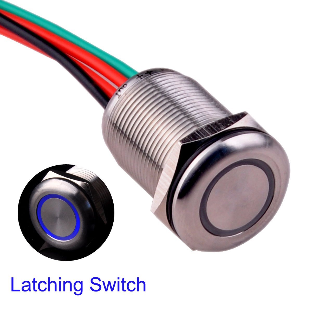
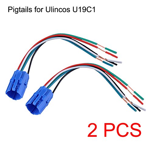
Ulincos wiring diagram. If the coil is not activated 30 will always be connected to 87a. Connect the 10k ohm resistor to no2 then connect it inline to ground. Looking at the diagram we see the pinout of a typical 12v relay. 19mm pigtail wire connector socket plug for u19c1 u19c2 u19c3 push button switch. Ut19t2 touch switch stepless dimming switch for 19mm hole. Auto relay u1914 with 14awg wire harness.
87 and 87a are the two contacts to which 30 will connect. But to be fair it did light up and would have been a fairly easy install again had the wiring diagram been. 30 day money back guarantee for any reason you may return your undamaged product and. About the wire harness five 14awg wires rated for 20a. Black 85 to ground white 86 to switch or trigger blue 30 to battery positive red 87a normally closed contact yellow 87 normally open contact whats note the relay is rated for 30a while the socket 14awg wires are not big enough for the rated 3040 amps. 19mm pigtail wire connector socket plug for u19c1 u19c2 u19c3 push button switch.
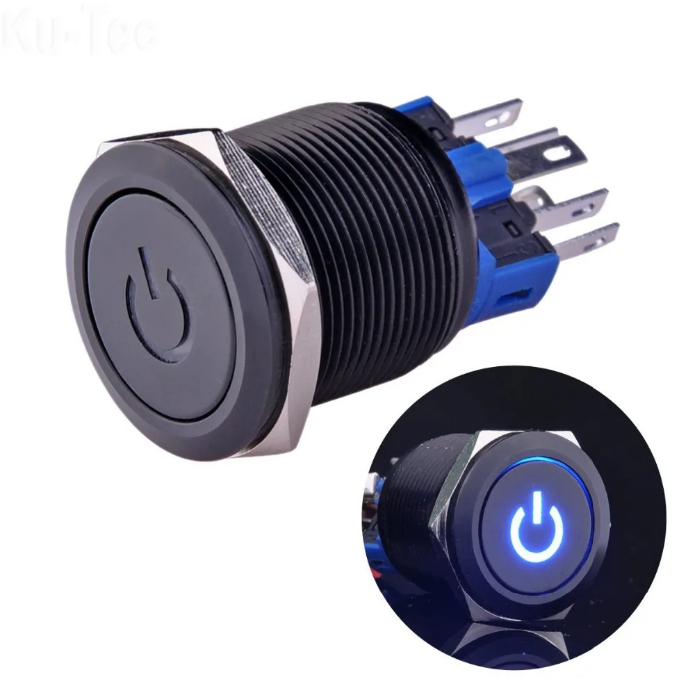
The diagram is a little bit messy but it shows how the button is connected to the arduino. 85 and 86 are the coil pins while 30 87 and 87a are the contact pins. Had it been correct i wouldnt have had to re solder it to find the correct way which didnt matter because after so many solders the button is now fixed on the off position thus. Wiring diagram was incorrect. Note that each pin is numbered. Halo switch or led latching switch wiring explained link.
Ut19t1 touch switch stepless dimming switch for 19mm hole. First connect no1 to positive then led to ground.
Gallery of Ulincos Wiring Diagram