Manual ups wiring diagram with change over switch system. Automatic ups system wiring circuit diagram for home or office.
Inverter Wiring Diagram For House Automatic Ups Inverter
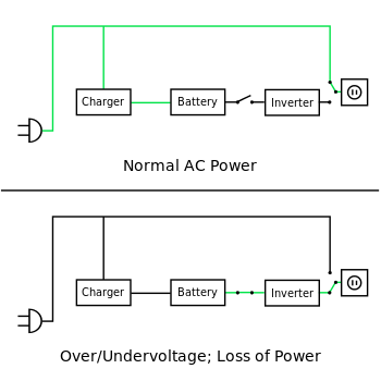
Ups wiring diagram for home. Now backup light is working when electricity is on but when it is gone backup light doesnt turn on. Automatic ups system wiring diagram in case of some items depends on ups and rest depends on main power at office or home. The small ups under an office desk is an n configuration. A wiring diagram is a simple visual representation of the physical connections and physical layout of an electrical system or circuit. It shows the elements of the circuit as simplified forms and the power as well as signal connections in between the gadgets. A wiring diagram typically provides information regarding the relative position and also plan of tools and also terminals on the tools in order to help in building or servicing the tool.
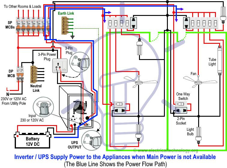
Likewise the 5000 square foot 465 square meters computer room with a projected design capacity of 400 kw is an n configuration whether it has a single 400 kw ups or two 200 kw ups paralleled onto a common bus. Collection of ups maintenance bypass switch wiring diagram. Automatic ups system wiring circuit diagram for home or office new design with one live wire also read. Now according to the below ups connection diagram connect an extra wire phase to those appliances where we have already connected phase and neutral wires from power house db ie two wire as phase live as shown in the below fig. Is by far the most common of the configurations in the ups industry. The solar panel connection with solar charge controller shown in diagram.
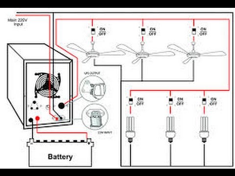
In the below ups wiring diagram. A wiring diagram is a simplified standard pictorial depiction of an electrical circuit. You can easily make a ups uninterruptible power supply at your home. Also a two 12 volts 150 watts solar panel shown which is connected in parallel connection. First we start from ups battery connection. Here a circuit diagram of ups is given.
Related electrical wiring tutorial. Recently i installed new upsinverter there all we did plug ups input to that same 3 pin socket and that single wire on left side of the ups output. From this ups you can get two power supply of different voltage one is 12v unregulated dc power supply and another is 5v regulated dc power supply. It is a very simple ups circuit diagram. It shows how the electrical wires are interconnected and can also show where fixtures and components may be connected to the system. In the diagram a 12 volt upsinverter shown with battery connection.
Manual ups wiring diagram with change over switch system. It is rented house so ups wiring is already present but no ups. Automatic ups system wiring circuit diagram for home or office new design with one live wire automatic ups system wiring diagram in case of some items depends on ups and rest depends on main power at office or home. Ups inverter wiring diagram with auto manual changeover switch system. Wiring diagrams for hardwire ups battery backup ups uninterruptible power supply systems in the following table can be directly wired to either a 120240 split phase panel 6k 10k single phase models or a 120208y 3 phase panel 10k 15k 20k 30k 40k 3 phase models.
Gallery of Ups Wiring Diagram For Home