6 wiring and mounting diagrams 16 61 act 5e prox wiring diagram for strike lock 16 62 act 5e prox wiring diagram for mag lock 17 63 mounting instructions for surface mount unit 18 64 mounting instructions for flush mount unit 19 7 user list 21 vanderbilt2018 3 a 100450 b 13062018. Vanderbilt keypad siemensbewator k42 keypad the v42 is still as popular as ever with an ip55 rating dual 12v 24v dc voltage input this fully featured self contained high security digital keypad is ideal for internal or external use.

Intercoms Audio Amp Video Intercom Phone Systems
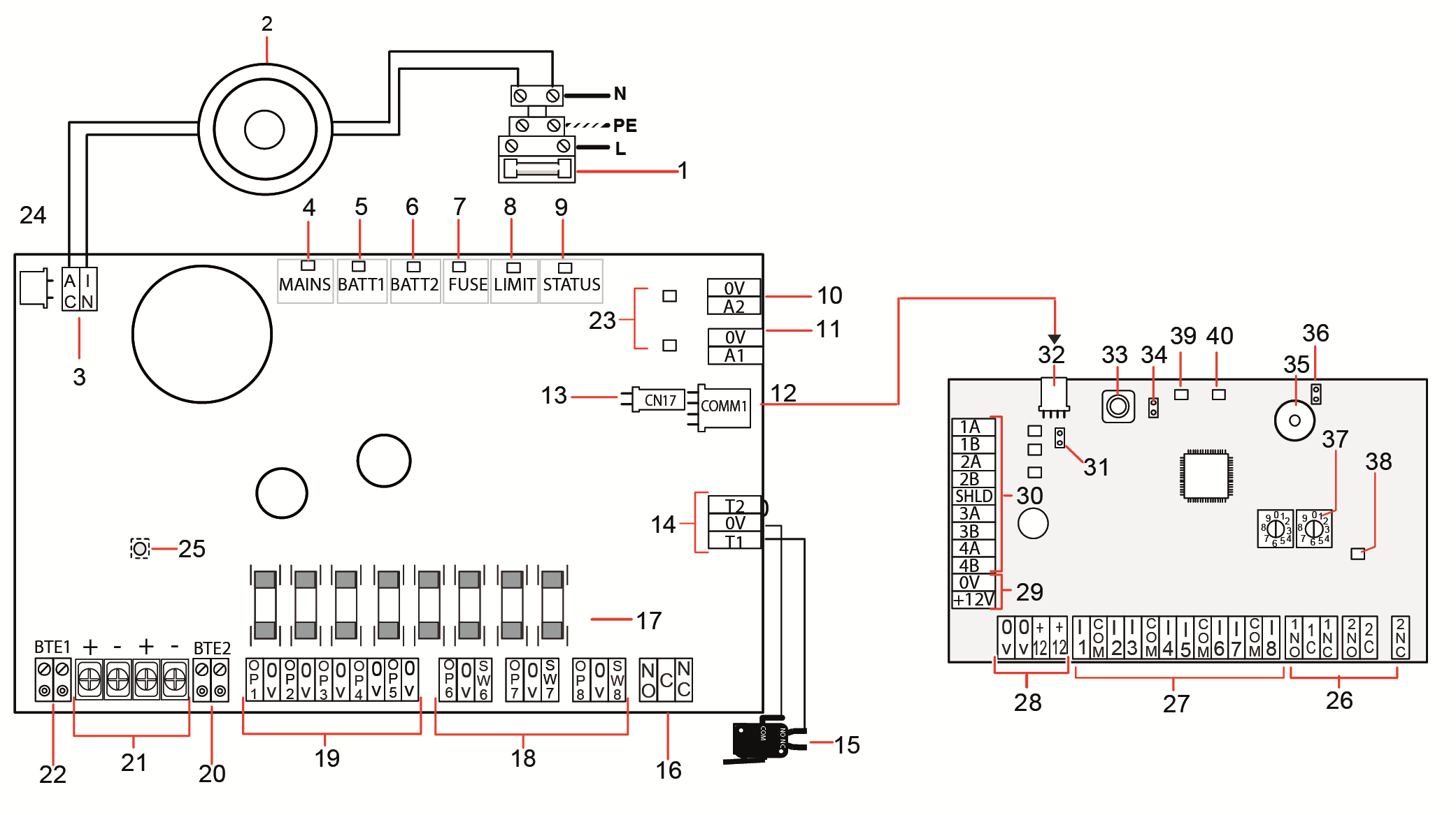
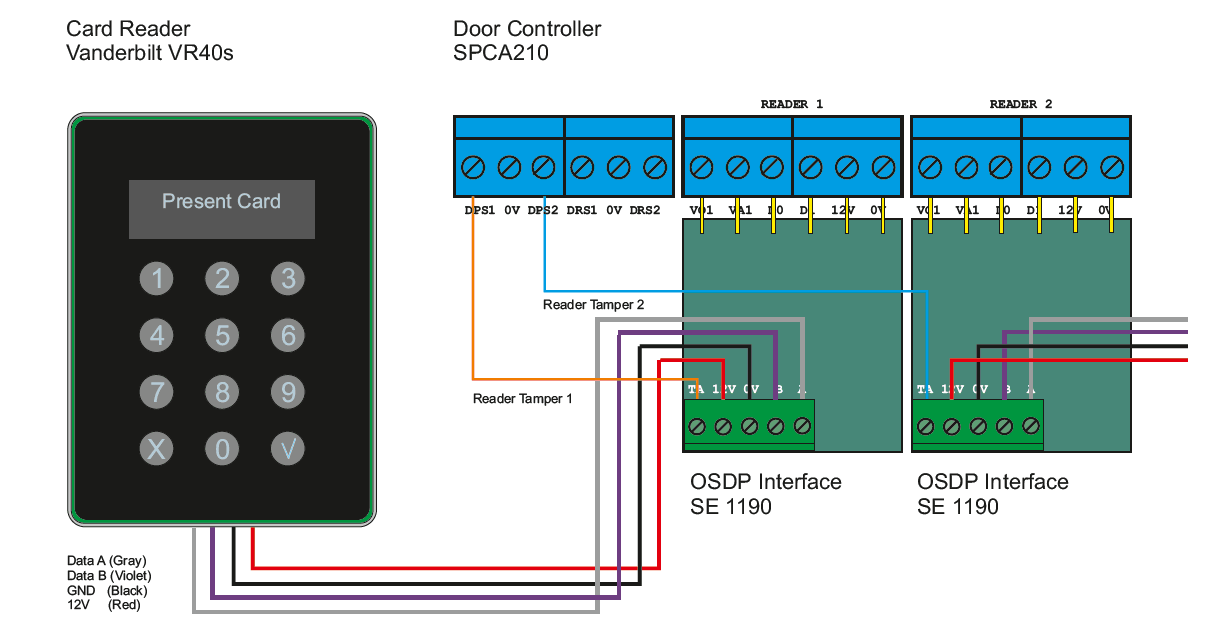
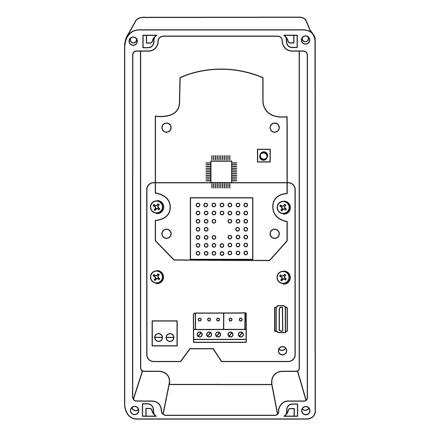
Vanderbilt keypad wiring diagram. Security products and systems. 3 keypad options 6 4 act 10 digital keypad programming 8 41 change user pin codes 8 42 set switched output combinations 8 43 set timers 9 44 set configuration 9 45 restore factory defaults 10 5 typical act 10 configuration 11 vanderbilt2018 3 a 100457 31012018. 3 act 5e digital keypad programming 6 31 change user pin codes 6 32 toggle relay 6 33 set relay active time 6 34 set the backlight 6 35 restore factory defaults 7 4 wiring and mounting diagrams 8 41 act 5e wiring diagram 8 42 mounting instructions for surface mount unit 9 43 mounting instructions for flush mount unit 10 vanderbilt2019. 4 wiring and mounting diagrams 41 act 5e wiring diagram notes. Keypad vanderbilt spck520 user manual 49 pages. The keypad may be returned to its factory default condition at any time by entering the programming mode and pressing the key three times.
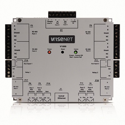
Connect the keypad to the arduino. A top brand keypad providing pin access. See wiring configuration in below. The keypad is now ready for normal use. Vanderbilt is designing and manufacturing state of the art security products and systems for access control and intrusion detection providing outstanding customer support. Voltage free relay max.
I f normally energised locks are required use the nc relay contacts. Sms bright blue and lite blue. The last connection is 1a 1b of the last expander to 2a 2b of the spc 5000 or 6000 controller. The keypad will enter lockout mode for 20 seconds. The wiring continues with connection 1a 1b to 2a 2b on the next expander and so on to the last keypad or expander. Incorrect code lockout when three invalid codes have been entered in a row.
The act 5e may be powered from 12 or 24v ac or dv. This is achieved by connecting 1a 1b on the controller to 2a 2b on the first keypad or expander. Follow the diagrams below to connect the keypad to an arduino uno depending on whether you have a 3x4 or 4x4 keypad. The pin layout for most membrane keypads will look like this. Pin code length 4 digit. From the diagram above you can see that the combination of row 2 and column 2 could only mean that the number 5 button was pressed.
K42 9 gb 6 relay terminal blocks for locks with failsafe power to lock function connect lock to terminal 5 not 3. Technical data power voltage. Access control intruder detection cctv and integrated security management. This illustration shows wiring for normally de energised locks.
Gallery of Vanderbilt Keypad Wiring Diagram