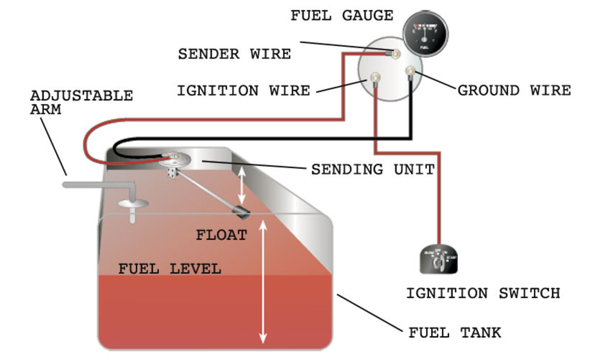
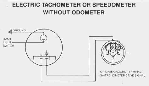
Connect the wire from. Refer to your vehicles ownerservice manual or the.

Troubleshooting Boat Gauges And Meters Boatus Magazine
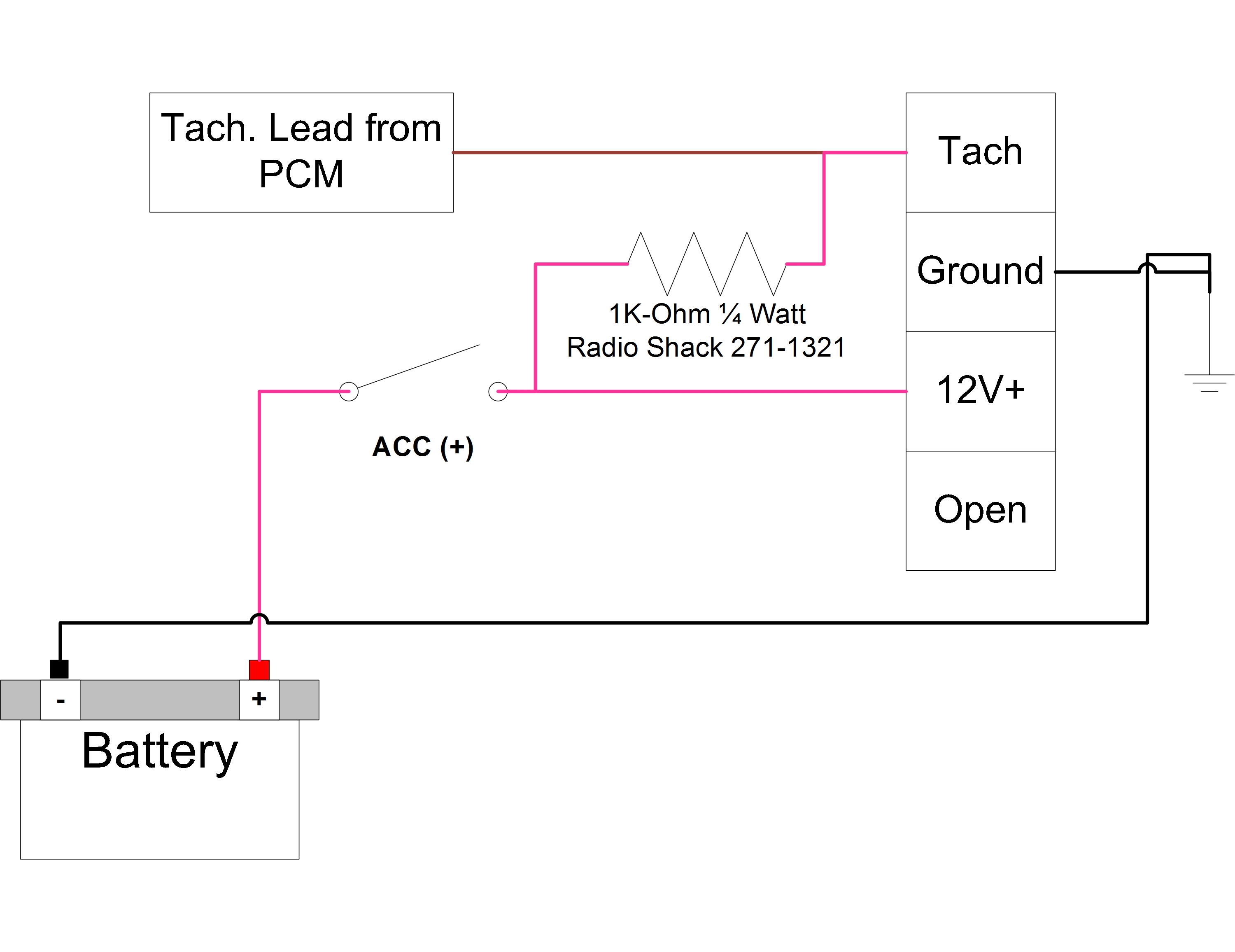
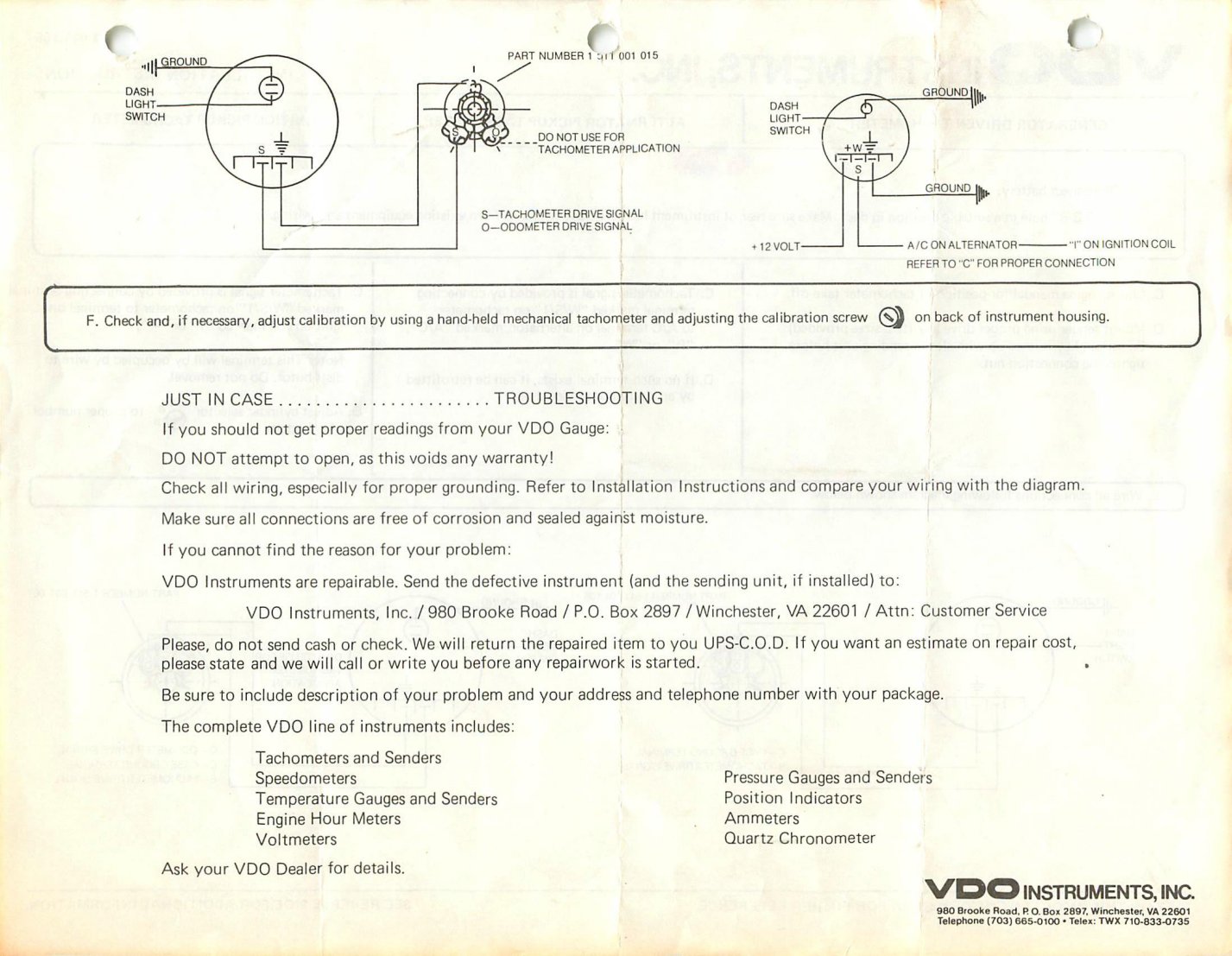
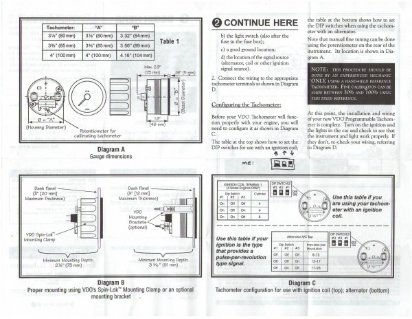
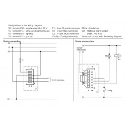
Vdo marine tachometer wiring diagram. Adjust the potentiometer on the back of the tach. Diagram f fine adjustment of the vdo tachometer when used with an alternator compare the vdo tachometer reading with that of a reference tachometer. Wire the tachometer to the vehicle as shown in either diagram c or diagram d. Shown in diagram c. Wiring the tachometer turn off the ignition and disconnect the negative terminal from the battery post if you havent already done so. 8 pin connection f1 fuse 5a quick response c1 8 pin mqs connector you must comply with the wiring diagram.
Related manuals for vdo tachometer. You may also mount the tachometer using an optional vdo mounting bracket and nuts. Mounting the tachometer 1. Vdo does not recommend mounting your xtreme 3. Make sure all wires are long enough to reach the necessary positive and negative terminals and any wires from the sensor. Hall effect sender 2012 hall effect sender 2012.
Measuring instruments vdo tachometer with counter installation instructions manual 11 pages measuring instruments vdo cancockpit series product manual. This section covers tachometers made by vdo sensor. When the vdo tachometer reading. New generation 2009 flexible instrumentation with can bus technology 174 pages. Tachometer without display 13 gb 14 connector set 8 pin a2c59510850 30 terminal 30 steady state plus 12 v 15 terminal 15 connected ignition plus 58 terminal 58 lighting 31 terminal 31 ground designations in the wiring diagram. Viewline marine tachometer 2014 voltage resistance chart 2004 voyager cluster wiring schematic 2005.
Viewline 52mm wiring diagram 2014 viewline level gauges 1224 volt 2011 viewline level gauges 52mm 2008. Prepare insulated ¼ spade terminals for use with the tachometer. Diagram e proper wiring of the vdo programmable tachometer with typical ignition systems ˇˆ ˇ.
Gallery of Vdo Marine Tachometer Wiring Diagram