They can be used with single or three phase motors. It turns the relay on for 3 to 10 sec varible and then turn the relay off and when again i push.
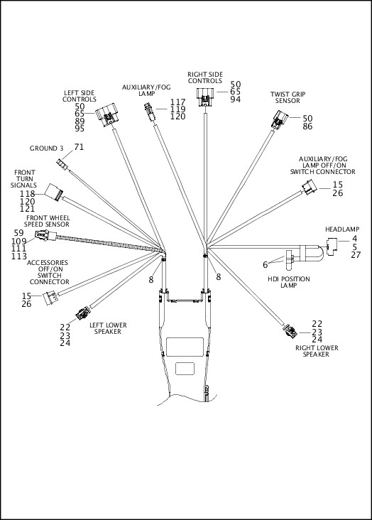
Engine Assembly Twin Cam 110
Ventair run on timer wiring diagram. A wiring diagram is a streamlined conventional photographic depiction of an electric circuit. The above wiring would instantly take care of the issues as now the output would switch after some time during power witch ons allowing enough time for the internal relays to settle down with the correct voltages across their output contacts. The typical elements in a wiring diagram are ground power supply cable and also connection result devices buttons resistors logic entrance lights and so on. Run on timers wiring diagram technical data direct wired technical data model number run on time start delay max. Amps enclosure size mm vz2 10ts 2 10 min na 5 153w x 110h x 60d the vz2 10ts plug in run on timer is designed to permit the supply of electricity to motors so they can continue to operate for a predetermined time. To read a wiring diagram first you have to know what essential aspects are consisted of in a wiring diagram and also which pictorial icons are utilized to represent them.
Run on timer with a va controller. 1 x run on timer all ventair exhaust fans new or existing exhaust fans a 5mm b 42mm c 25mm b a c dimensions model outer carton ean13 barcode celt7mintimer 19339310001963 61 3 9775 0556 61 3 9775 0775 sales. Continues to eleminate steam and odour after leaving the room. Many pool pump motors and water heaters use intermatic timers to regulate their run times. An intermatic timer switch saves electricity when it turns a water heater off at night and when it limits the amount of time a pools filtration system runs. Assortment of time delay relay wiring diagram.
Intermatic incorporated manufactures timer switches designed for indoor and outdoor use. Wiring diagram technical data model number run on time start delay max. On delay timers can easily be identified in ladder diagrams. On delay timer coils are represented like all loads illustrated ladder diagrams except there is a label with the abbreviation of td which stands for time delay and the contacts are drawn like a single pole switch with two legs coming out of the bottom as seen in figure 1. It reveals the elements of the circuit as simplified shapes as well as the power and also signal links between the gadgets. Extractor fans with an integral timer or timed switch need a 3 core and earth supply to allow the unit to run on after a light is switched off.
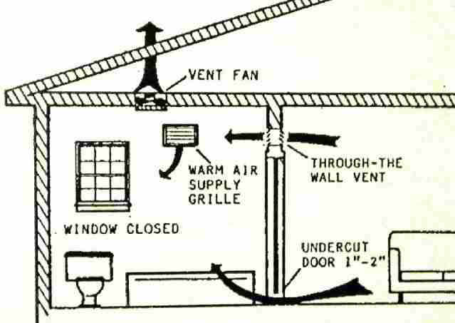
Amps dimensions mm vz24c up to 24 min up to 150 sec 125 32w x 13h x 17d vz6 6 min 50 sec enclosure rating ip40 direct wired technical data model number run on time start delay max. The timer module is designed to fit within a wall mounted electrical flush box or alternatively is located within a fan assembly. It must also be possible to isolate the fan by means of a pull switch inside the bathroom or a fan isolation 3 pole switch outside of the bathroom. Fully adjustable 1 25 minute exhaust fan timer.
Gallery of Ventair Run On Timer Wiring Diagram