A wiring diagram is a simplified standard photographic depiction of an electric circuit. It shows the parts of the circuit as streamlined forms and the power and also signal links between the gadgets.
Variable Frequency Drive Mysweety Vfd Inverter Frequency Converter 2 2kw 3hp 220v 12a For Spindle Motor Speed Control Vfd 2 2kw
Vfd motor wiring diagram. A wiring diagram is a streamlined standard photographic depiction of an electric circuit. We use the 2 wire method for controlling the speed and direction of the motor. Run wires from vfd to motor. It reveals the components of the circuit as simplified forms and also the power as well as signal connections in between the gadgets. A wiring diagram is a streamlined traditional pictorial representation of an electrical circuit. Collection of abb vfd wiring diagram.
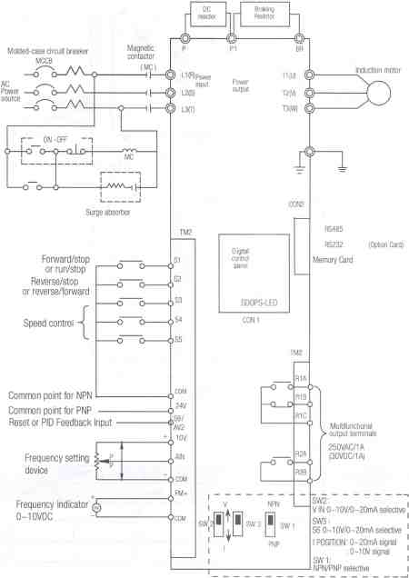
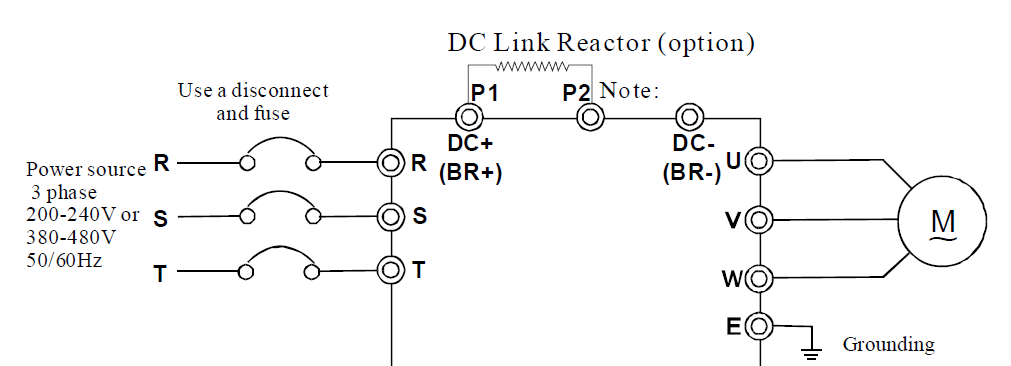
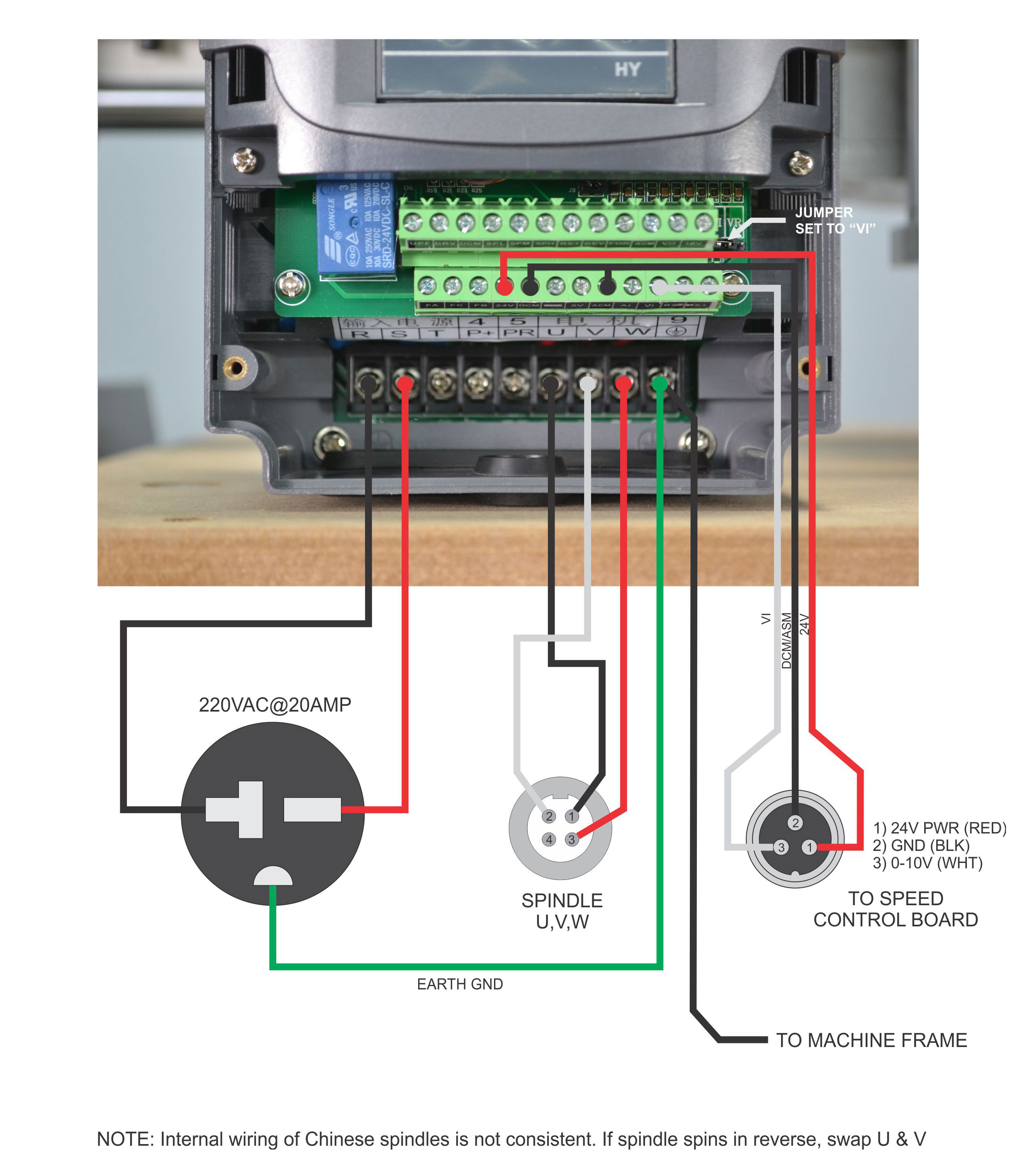
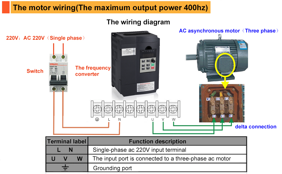
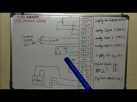
Main circuit wiring the vfd main circuit terminals shown as below figure. 1 the vfds three phase ac input terminals rl1 sl2 tl3 the power lines input terminals connect to 3 phase ac power through line protection or leakage protection breaker it does not need to consider the connection of phase sequence. Use proper raceway as you see fit. A vfd can be used to vary speed direction and other parameters of a 3 phase motor. Connect or do wiring as per vfd side drawing you take 24 v from the vfd pcb directly. A wiring diagram normally offers details concerning the loved one setting and setup of devices and also terminals on the tools to assist in building or servicing the tool.
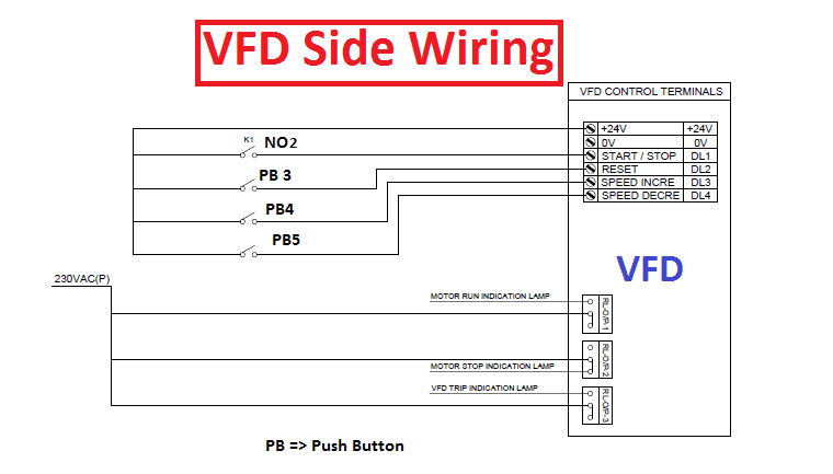
Then k1 no1 become no vfd stop output voltage. A wiring diagram usually gives details about the loved one position and setup of gadgets and also terminals on the devices in order to help in structure or servicing the gadget. Makeup wires in your motor. Land wires in conduit box on motor. Learn the basic wiring of variable frequency drives vfd with our electrician steve quist. When you press stop push button 2 then k1 contactor get release.
Then as per vfd logic if dl 1digital logic goes high vfd start to feed the output voltage motor start rotating. Working of a vfd. Motor will be stopped. Vfd start stop wiring diagram. Assortment of vfd wiring diagram. When you press the on push k1 contactor will hold and k1 no1 become nc.
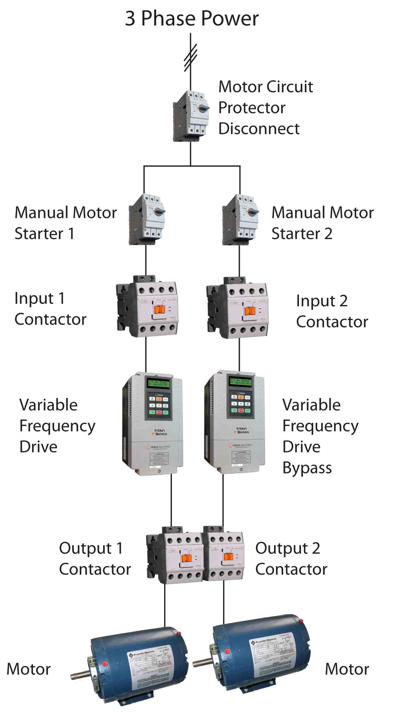
Use the wiring diagram on your motor to determine the correct wiring method. In this video we used the very popular mitsubishi d700 series vfd showing single phase and three phase wiring instructions. Vfd wiring best practices introduction with a growing need for saving energy variable frequency drives are being used in many general purpose applications where they are controlling 3 phase electric motors. Use the same gage wires as you did from the circuit breaker to the vfd. How to wire a 3 phase motor and vfd duration. It reveals the elements of the circuit as streamlined shapes and also the power and signal connections between the devices.
K1 no1 pb3 pb4 pb5 should be of potential free contact. Variety of vfd motor wiring diagram. The vfds showed in the video are the d720s 230v single phase and the d720 230v three phase. We strongly recommend using a certified electrician to set up your vfds. United states restricted mode. With the use of the vfd not only saves energy but also saves the life of motors by providing a soft start and advanced process control.
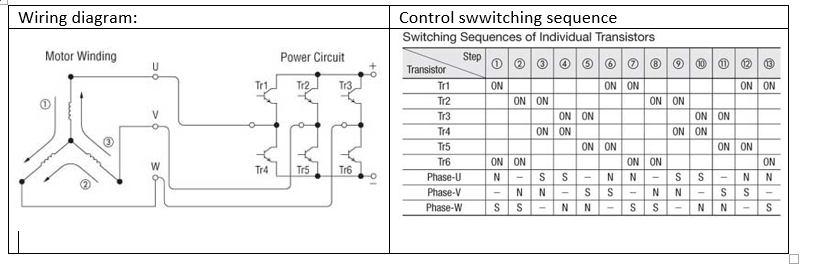
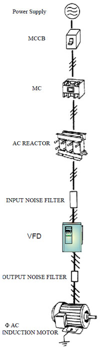
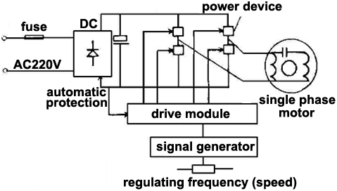
The first stage of a vfd is the converter which comprises six diodes which are similar to check valves used in plumbing systems.
Gallery of Vfd Motor Wiring Diagram


.png)