We use cutting edge technology to make sure you are in control providing range and features you can count on every time. Each part ought to be set and connected with different parts in specific way.
D37 2005 Dodge Viper Wiring Diagrams Wiring Library
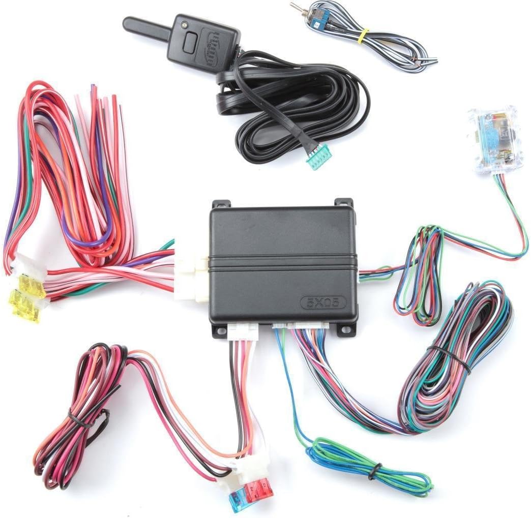
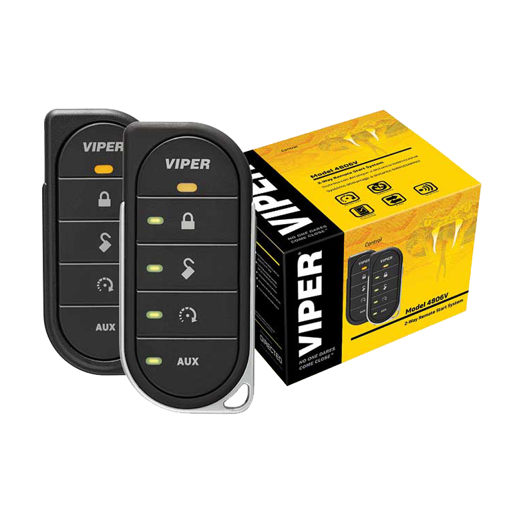
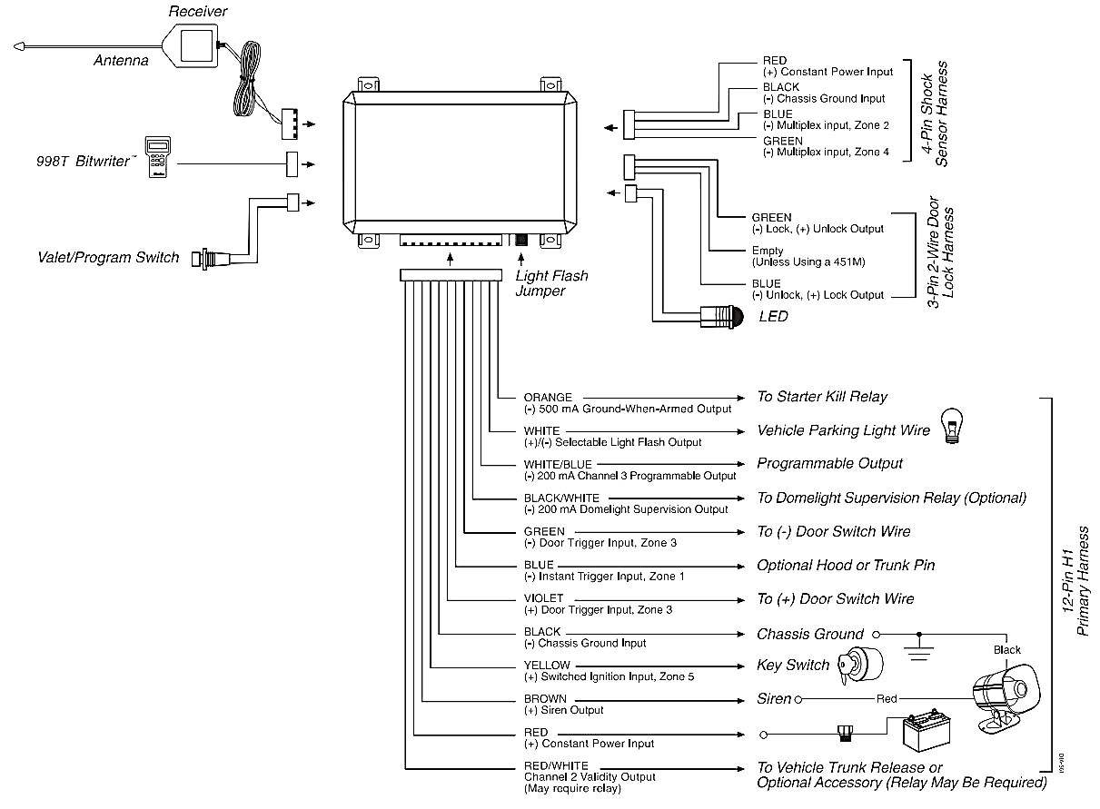
Viper 3106v wiring diagram. If not the structure wont function as it should be. Viper is the worlds best selling vehicle security and remote start brand. Viper is the most recognized name in vehicle security and auto remote start systems and an industry leader in cloud connected car technology. See directfax document 1076 for wiring instructions. 1 viper way suite 101 vista ca 92081. Wiring diagram bitwriterdirected smartstart port d2d port for external directed interface module detail optional mux port gwa zone 4 optional mux port zone 7 1 1 1 8 1 7 1 3 10 12 control center rfcontrol center port door lock 8 pin harness auxiliary 7 pin harness starter disable harness main 12 pin harness note.
Also included are possible applications of each wire. What our customers say. Viper products include car alarms remote car starters wireless home security and automation window film window tint smartstart interface modules accessories transmitters and remotes. Fuse is under the. A dual diode harness assembly is provided viper model only for european vehicles which have parking light capability for illumination of only the parking lights on the side of the vehicle to the road when parked. Primary harness wiring diagram primary harness wiring instructions this guide describes in detail the connection of each wire.
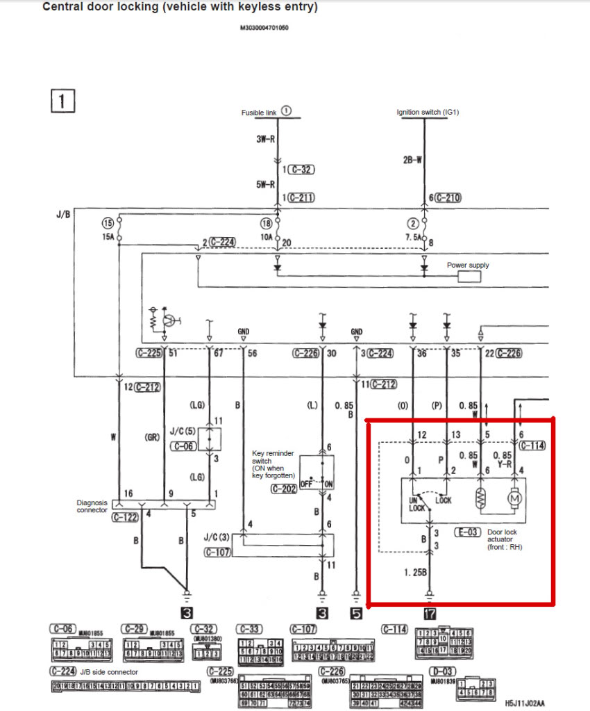
Assortment of viper 5305v wiring diagram. 350 plus installation guide note. Any attempt to install this product by any person other than a trained professional may result in severe damage to a vehicles electrical system and components. It shows the parts of the circuit as streamlined shapes and also the power as well as signal connections between the gadgets. Viper 5706v wiring diagram every electric structure is composed of various unique pieces. A wiring diagram is a simplified traditional pictorial representation of an electrical circuit.
2008 directed electronics vista ca. When adjusting the sensor it must be mounted in the same loca tion where it will be after the installation is completed. Adjusting the sensor and then relocating the module requires readjustment. Auxiliary harness wiring. This system was designed with the ultimate in flexibility and security in mind. Bypassing sensor inputs sensors can be bypassed during auxiliary channel and add on accessory op erations.
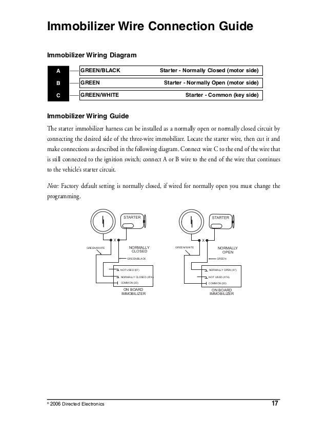
This wire will report zone 3. The recipient of nearly 100 pat ents and innovations awards in the field of advanced electronic technology. Many of the wires have more than one. This product is intended for installation by a professional installer only.
Gallery of Viper 3106v Wiring Diagram