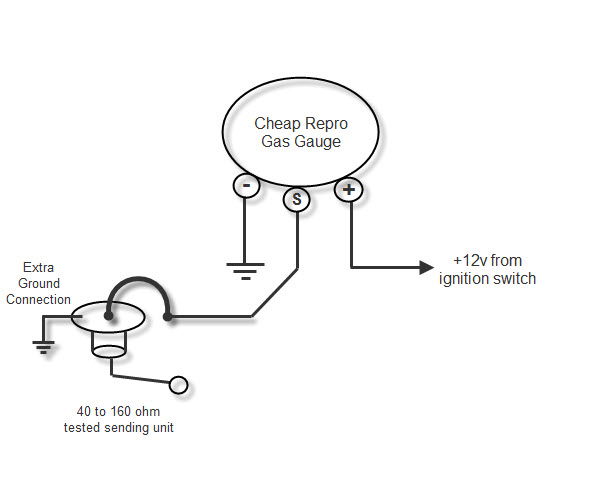
A wiring diagram is a simplified traditional photographic representation of an electric circuit. After you have mounted the gauge connect the sender wire to the left connection post as shown in diagram 2.

Boat Amp Meter Wiring Diagram Troubleshooting Teleflex
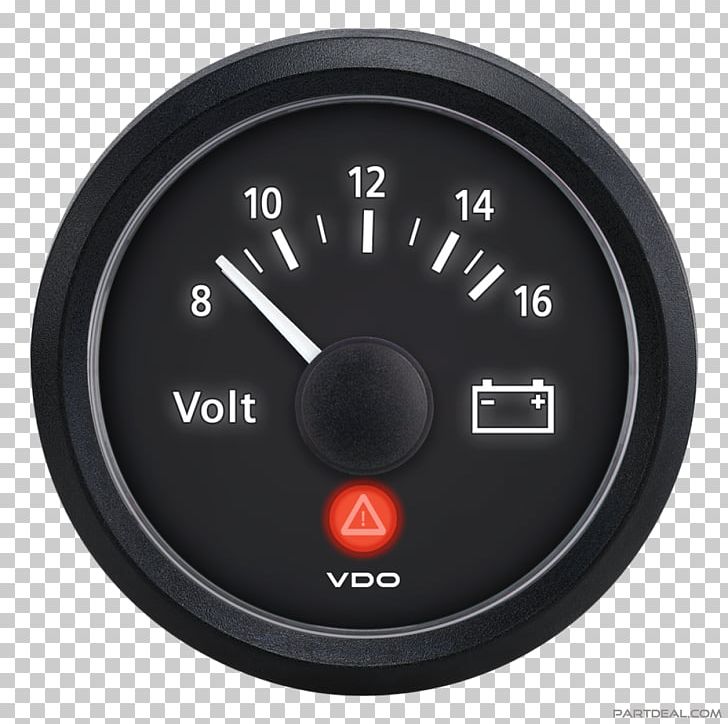
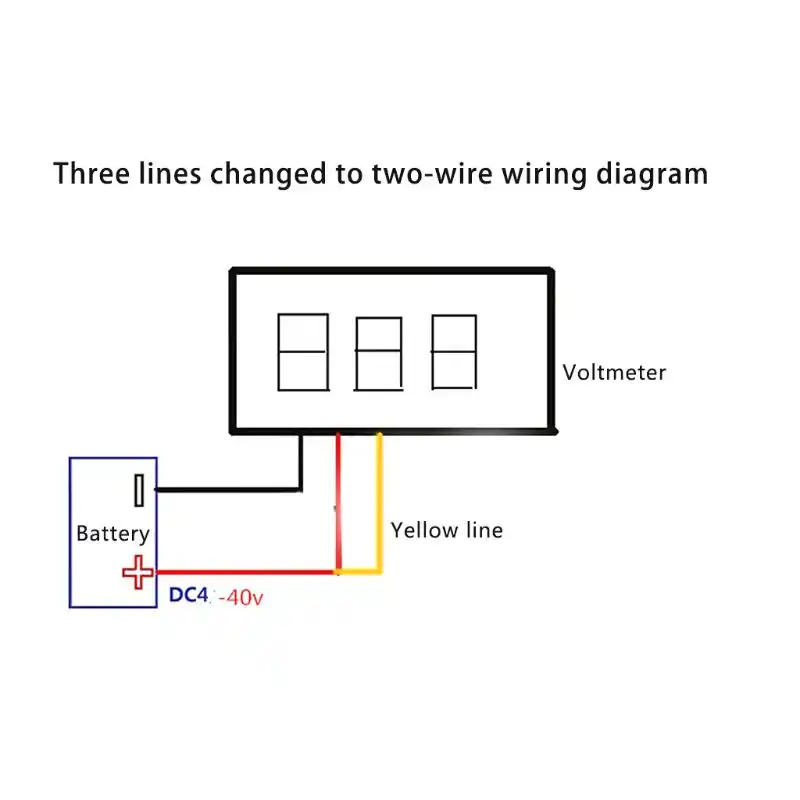
Volt gauge wiring diagram. If in doubt please contact your dealer or vdo. Step 6 connect positive wire. Autometer voltmeter wiring diagram perfect modern voltmeter gauge autometer gauge wiring diagram. Take the negative wire from the voltmeter and make a good connection on a grounded screw in the car. Connect the end coming from the steering column to the voltmeter. Voltmeter gauge wiring diagram in car amp meter voltmeter gauge wiring diagram wiring diagram is a simplified customary pictorial representation of an electrical circuit.
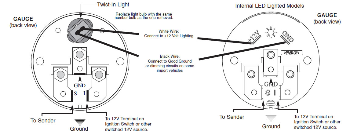
Do not deviate from assembly or wiring instructions. Wiring diagram not just offers detailed illustrations of everything you can perform but in addition the processes you ought to stick to whilst carrying out so. S standard ground floating ground s. Not merely can you locate various diagrams however you also can get step by step. Always disconnect battery ground before making any electrical connections. Facing the back of the gauge the connection post on the right is for the 12 volt power the center post is for the ground connection and the left post is for the sender connection.
It reveals the elements of the circuit as simplified forms and the power and signal connections between the devices. It shows the components of the circuit as simplified shapes and the facility and signal contacts with the devices. Use one of the wires that you found in the wiring harness and cut it between the steering column and connector in the dash. Assortment of volt amp meter wiring diagram.
Gallery of Volt Gauge Wiring Diagram