Heat recovery 575v vrv aurora. System air conditioner rxsq60tavjua.
Wiring Diagrams Docs Hvacpartners Com
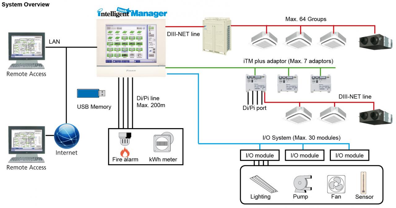
Vrv wiring diagram. Vrf system control wiring. Vrv iv rxyq 575v. Vrv iv rxyq. Heat pump 208 230v. The wiring between the outdoor units should be connected by extending the attached cable using the included connectors. This control wiring layout is similar amongst the other vrf manufactures.
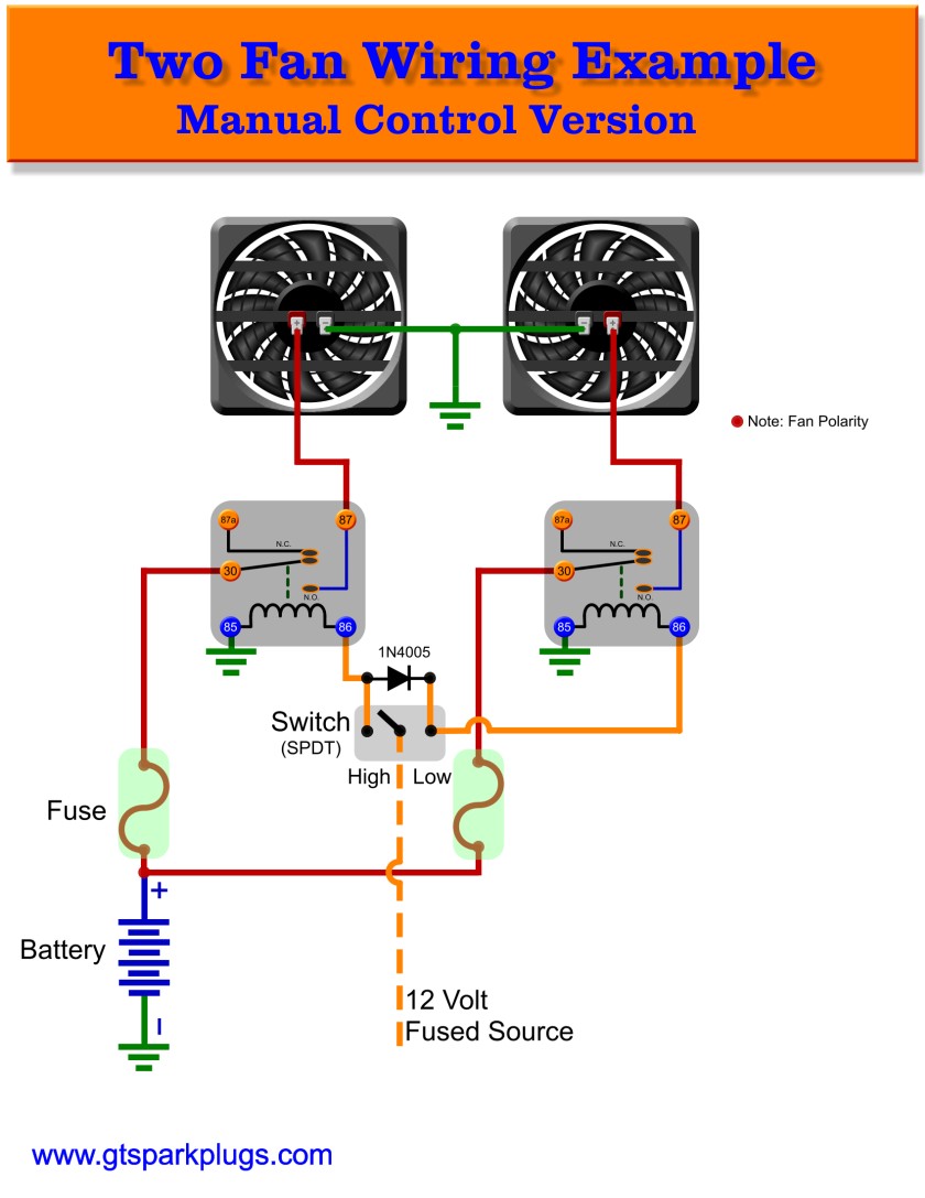
The control wiring is very simple its basically two 18 gauge wires that go from the thermostat to the fan coils wire 1 so that each zone will have a wire from the thermostat to the fan coilone controller thermostat can control more than one indoor. Vrv life rxsq60tavjua. Improper positioning of the electric parts box lid may result in electric shocks fire or the terminals overheating. This vrf system control wiring is for a vrf vrv heat recovery system with single port branch selector boxes. Heat pump 575v vrv iv x reyq. Page 28 installation field wiring vrv plus 2 4 4 field line connection between main unit rxyp and sub unit rxep rsxyp24262830 1.
Refrigerant piping intake power supply wiring intake knockout hole ø34 transmission wiring intake knockout hole ø27 drain pipe connection od ø26 anchor point bolt 4 m12 installer and user reference guide rxysq812tmy1b vrv iv s system air conditioner 4p404225 1b 201603. Cable low voltage 2. When wiring the power supply and connecting the remote controller wiring and transmission wiring position the wires so that the electric parts box lid can be securely fastened. L1 l2 l3 20a 3ph 34 c 4 10 thhn 1 10 cu. Rxyp1620 main unit 11. Vrf vrv simple control wiring for a heat recovery system using single port branch selector boxes.
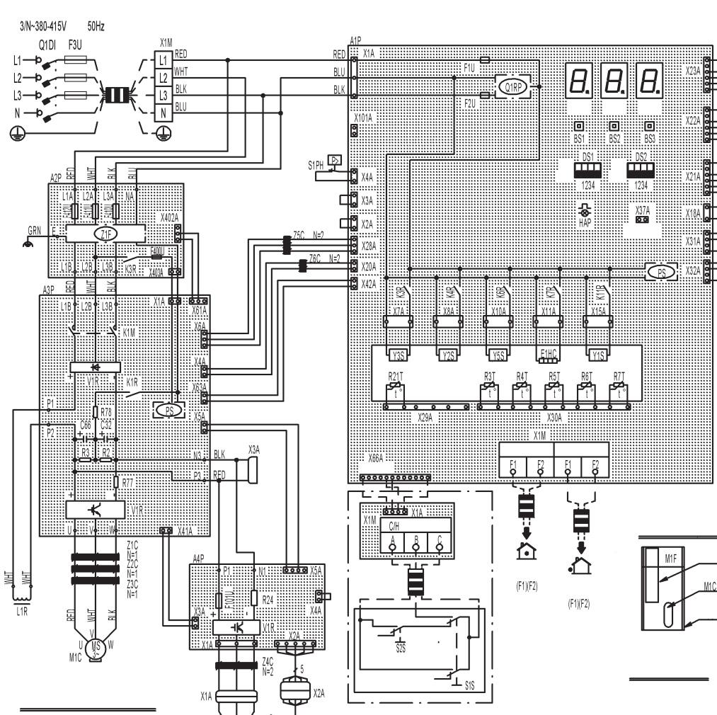
Vrv iv reyq 575v. Heat pump 208 230v 460v vrv iv x rxyq 575v. 1 daikin vrv wiring diagram m4 nts hp 1 reyq336pbyd remq120pbyd remq96pbyd remq120pbyd q1q2 q1q2 q1q2 l1 l2 l3 21a 3ph 34 c 4 10 thhn 1 10 cu. Heat pump 575v vrv iv reyq. Vrv iv x rxyq.
Gallery of Vrv Wiring Diagram