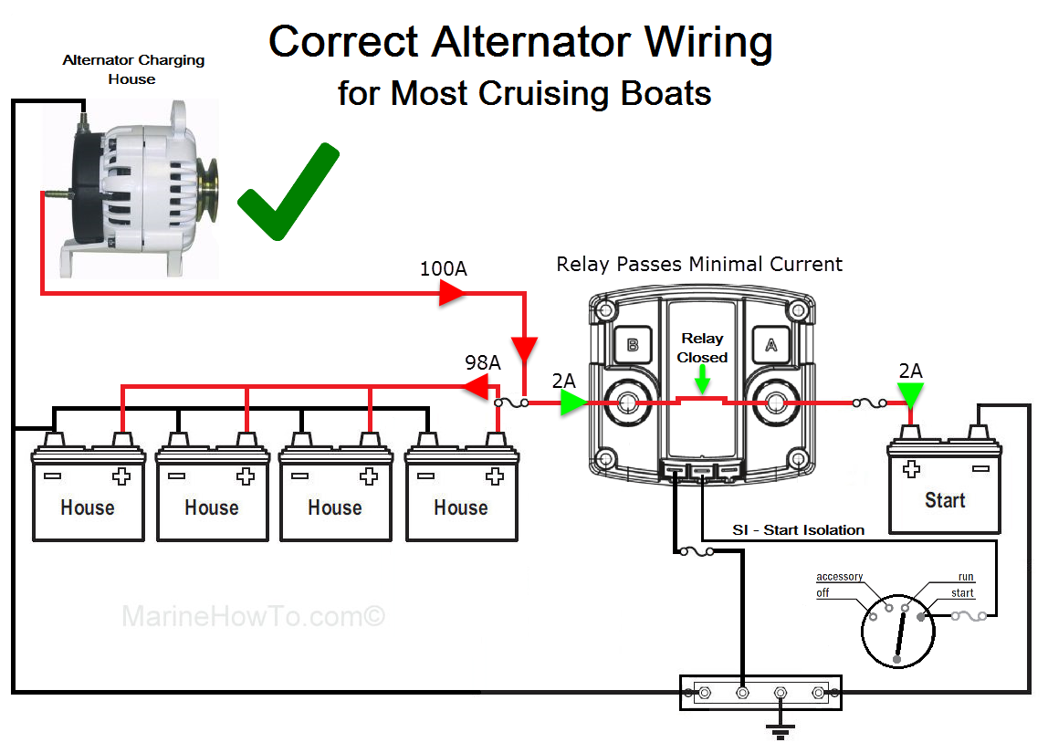
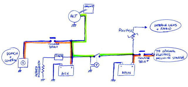
A super simple wiring diagram on how a split charge device directs power towards the leisure battery one it has been engaged. Have a look at the diagram above to see the basic wiring diagram of your voltage sensed split charge kit.

Ht 3629 Wiring A Voltage Sensitive Relay Free Diagram
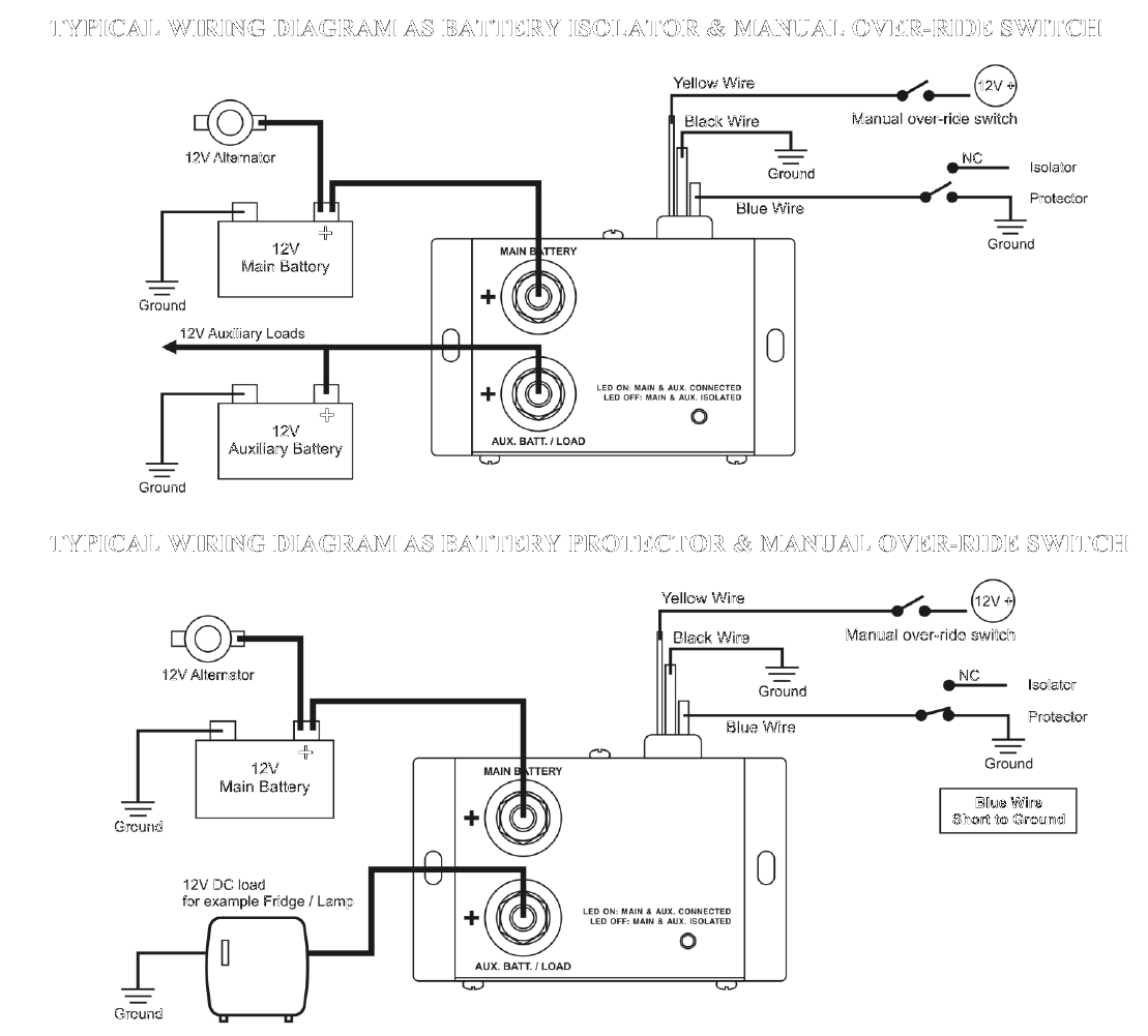
Vsr split charge wiring diagram. Automatically charges a second battery bank from any single charging. A typical campervan split charging system has a device that connects the battery used to start the engine to the leisure battery when the engine is running. It is vital to follow the wiring installation diagram which shows correct connection to the master switch. 12 volt planet is an online supplier of low voltage electrical components and. 2 3 connect the thin black earth wire from the vsr to the vehicle chassis or the starter batterys negative. Care should be taken if using this feature for engine starting as starter motors can draw very high currents so the switch should be rated sufficiently.
In this video we explain the differences between voltage sensitive relay vsrs and battery to battery chargers. Connect the negative wire of the long cable to the negative wire coming from the start battery. Dual battery charging made easy. If your split charge device does not already have this facility then you might want to consider adding a manual battery switch to the circuit to by pass the split charge device. 4 connect the positive ring terminal of the included long cable to the unmarked silver terminal of the vsr. I have misplaced the diagram i had when i first installed the system when i had the johnson dec 02 12 volt relay wiring diagrams durite vsr split charge relays 12v having completed the camper interior of the van it was time to hook up a second battery to provide power in the back of the van.
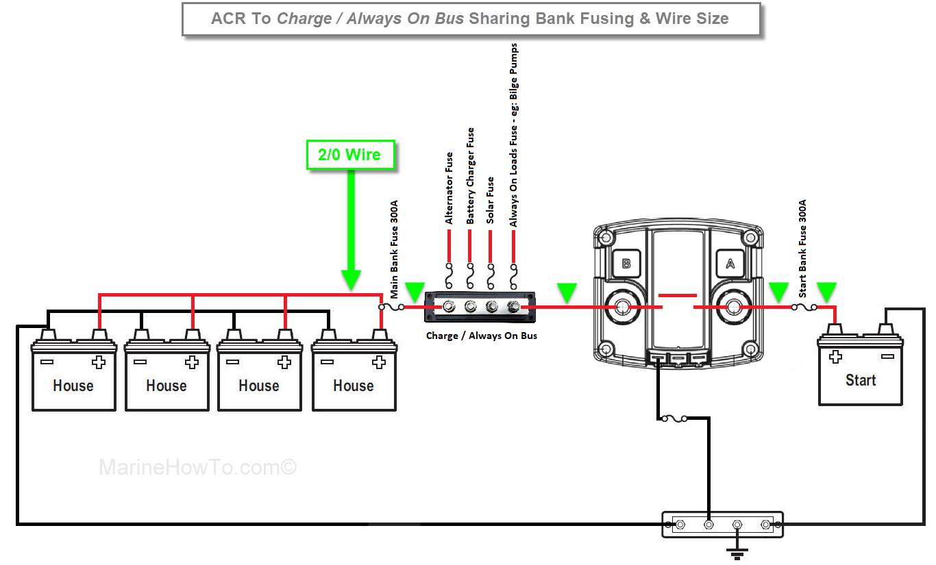
Instillation guide for a 12v voltage sense split charge relay system thank you for purchasing this kit from simply split charge. Split charge kit installation instructions split charge system layout starter battery leisure battery vsr fuse holder 1 cable 1 cable 2 cable 4 note. Wiring diagrams dvsr conections house b a t t positive s t a r t b a t t positive. Acts like a single sensing vsr as dvsr will only activate when engine alternator is charging. Only for installation in 12v dcsystems where the vehicle chassis is the groundnegative na to boats 1. The 7 0 25a ds is designed for situations where a battery charger or second charging source is used into the house battery.
To which side of the battery switch should the vsr be wired. Could you be kind enough to send me a wiring diagram so i can correctly connect the vsr relay and guest switch for the 2011 e tech 90 engine. Bep only recommends the supplied option. Importantdis connect the ve terminal clamp from the starter battery and the. I have misplaced the diagram i had when i first installed the system when i had the 1984 johnson 70. I have left boxes on the diagram on the left to help you with your measurements.
Gallery of Vsr Split Charge Wiring Diagram