It is a red wire and comes from the transformer usually located in the air handler for split systems but you may find the transformer in the condensing unit. A wiring diagram is a simplified standard pictorial representation of an electrical circuit.

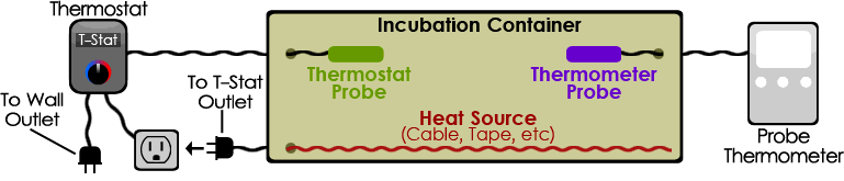
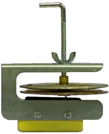
Poultry Incubator Wafer Thermostat
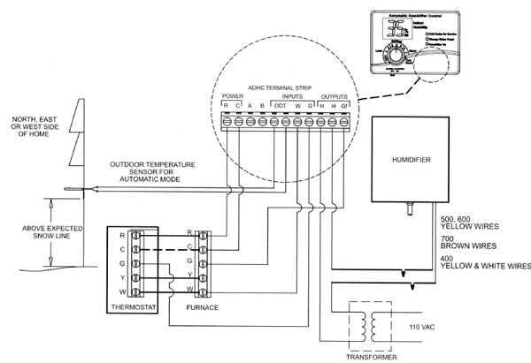
Wafer thermostat wiring diagram. Diagram 3 thermostat installation. Rc red wire power 24 vac rh or 4 red wire jumpered power 24 vac w white wire for heating enable y yellow wire for cooling enable. Nest heat pump wiring diagram. Collection of wiring diagram for hot water heater thermostat. The diagram below shows how a basic 4 wire thermostat is connected as indicated by the color code chart above. Yellow the yellow wire connects to your compressor.
W1209 thermostat wiring connections and temperature settings making video tamil. The water heater element is connected to the thermostat via t 2 as hot and l 4 as neutral. After warmup rapid cycling of thermostat on and off is normal. As i shown in the below electric water heater wiring diagram. Poultry incubator wafer thermostat duration. Thermostat wiring and wire color chart thermostat wiring colors code.
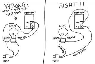
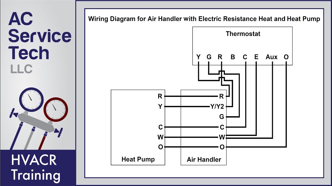
White the white wire is what connects to the auxiliary heat on your system. Green the green wire connects to the fan. Thermostat wiring diagrams for heat pumps heat pump thermostat wire diagrams. Heat pumps are different than air conditioners because a heat pump uses the process of refrigeration to heat and coolwhile an air conditioner uses the process of refrigeration to only cool the central air conditioner will usually be paired with a gas furnace an electric furnace or some other method of heating. Red now there can be two separate wires for this. Study wiring diagrams 1 2 and 3 shown below for installation of electronic thermostat and follow step by step instructions.
Black color is neutral while red is phase or line and the yellowgreen wire is used for ground earth. Orange this wire connects to your heat pump if you have one. 1 4 nut driver 1 2 drill bit 7 8 drill bit wire cutter wire stripper pliers. The line is connected to the l 1 terminal while neutral or second line is connected to the l 3 terminal. The wiring connection for both single phase 120v and 240v are same ie. R the r terminal is the power.
The basic heat ac system thermostat typically utilizes only 5 terminals. Electric water heater wiring methods and diagrams for double and single heater element with thermostat. Color of wire and termination. When upper water heater element done his work upper thermostat switch of the neutral wire to upper thermostat and provide the neutral wire to lower thermostat. It shows the elements of the circuit as simplified forms and also the power as well as signal connections between the tools.
Gallery of Wafer Thermostat Wiring Diagram