Wiring a switch to a wall outlet. Another reason to change out the switch is appearances.
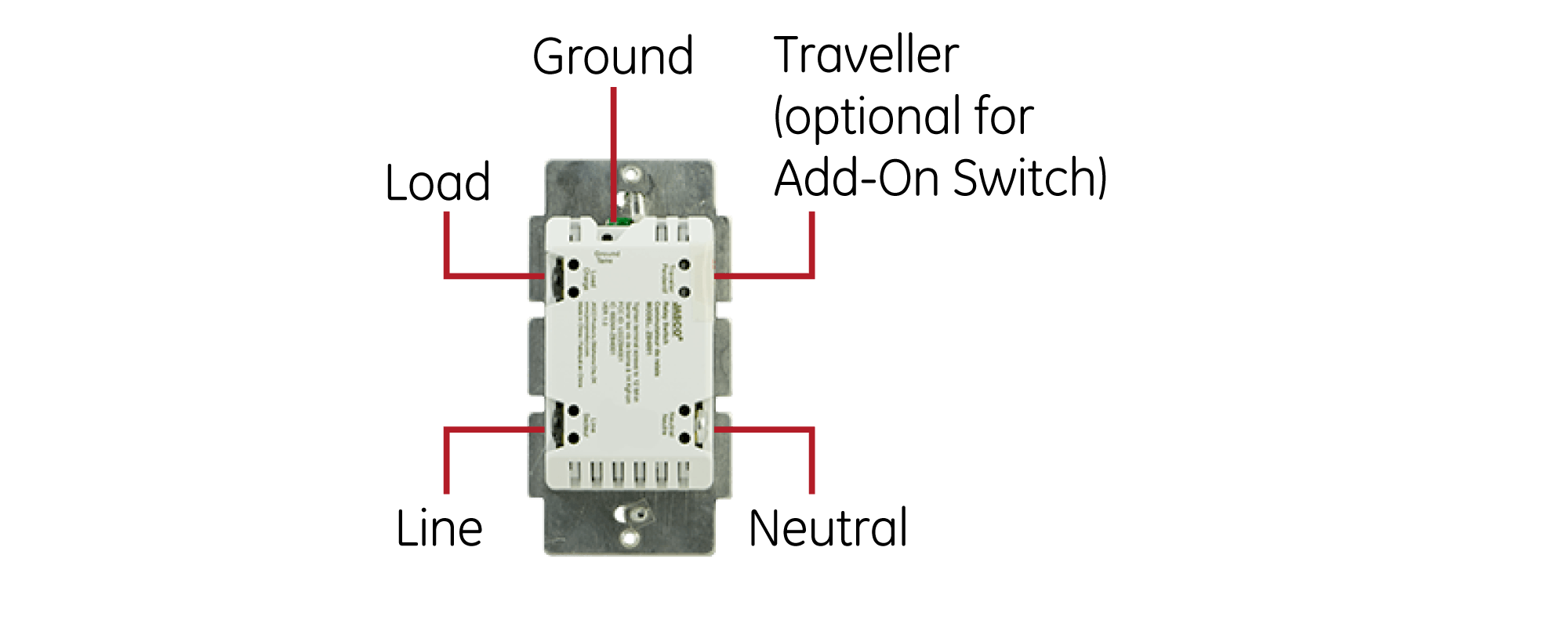
Ge Zigbee In Wall Smart Switch With Energy Monitoring
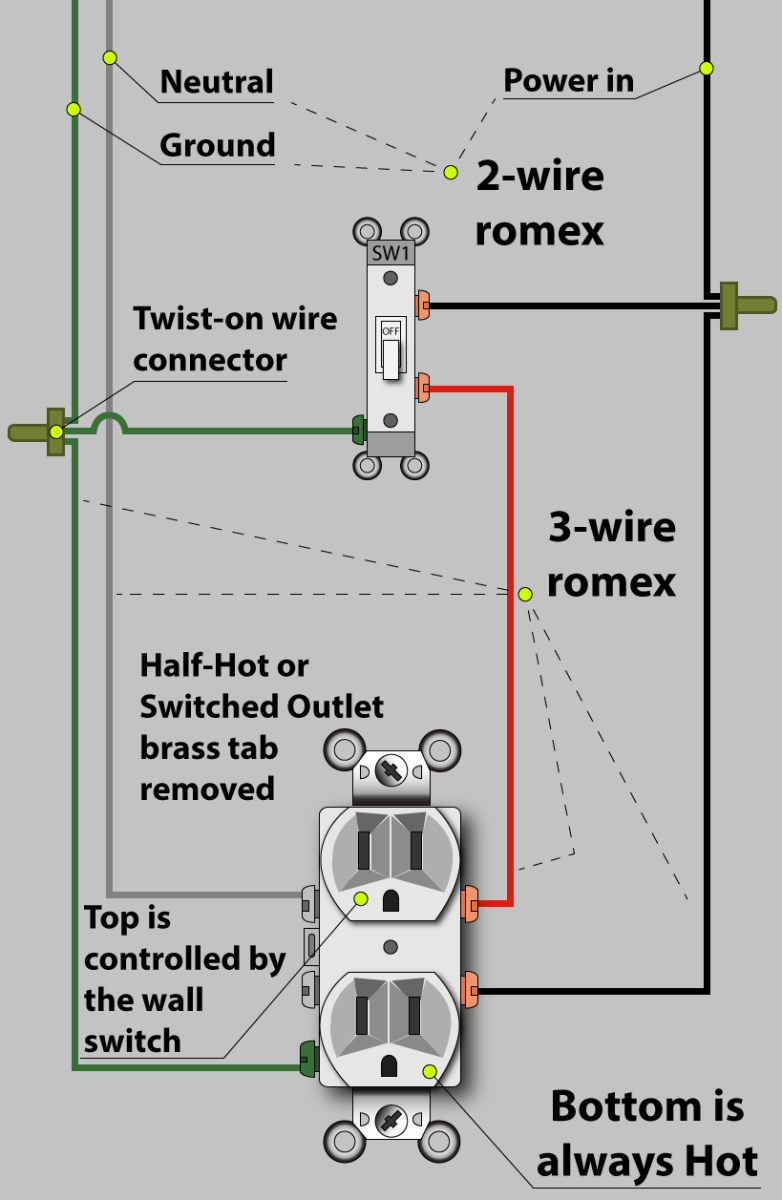
Wall switch wiring diagram. The source is at sw1 and the hot wire is connected to one of the terminals there. The source is at the outlet and a switch loop is added to a new switch. The black and red wires between sw1 and sw2 are connected to the traveler terminals. Still you will want to replace a switch when it wears out in part because it presents a fire hazard. Featuring wiring diagrams for single pole wall switches commonly used in the home. The hot source wire is removed from the receptacle and spliced to the red wire running to the switch.
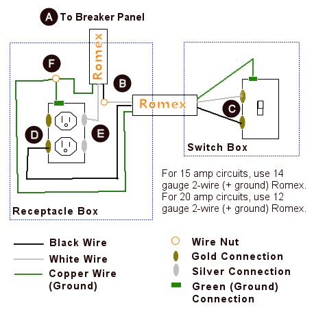
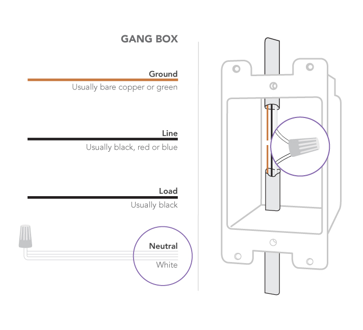
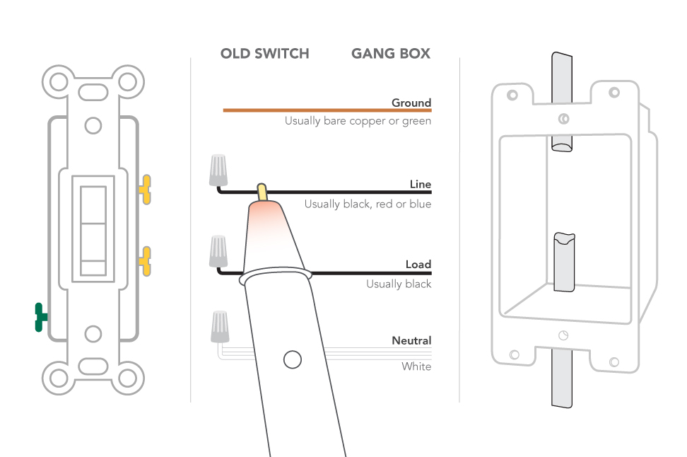
The black wire from the switch connects to the hot on the receptacle. Here a receptacle outlet is controlled with a single pole switch. In this diagram 2 wire cable runs between sw1 and the outlet. Three wire cable runs between the switches and 2 wire cable runs to the light. Circuit electrical wiring enters the switch box the black wire power in source attaches to one of the switch screw terminals fixture wiring exits the switch box the black wire power out wiring attaches to the. After you have pulled your switch out from the wall the wires in the box and connecting to the switch should look like one of the following.
So now that you have a basic concept of wiring a 2 way switch lets look at the following 2 way switch diagrams to see which type of circuit scenario you have. This wiring diagram illustrates adding wiring for a light switch to control an existing wall outlet. This is commonly used to turn a table lamp on and off when entering a room. Electric wall switches last a long time. Basic 2 way circuit power coming in at switch. You may want to change the size color or style of the switch.
In this diagram the electrical source is at the first switch and the light is located at the end of the circuit.
Gallery of Wall Switch Wiring Diagram