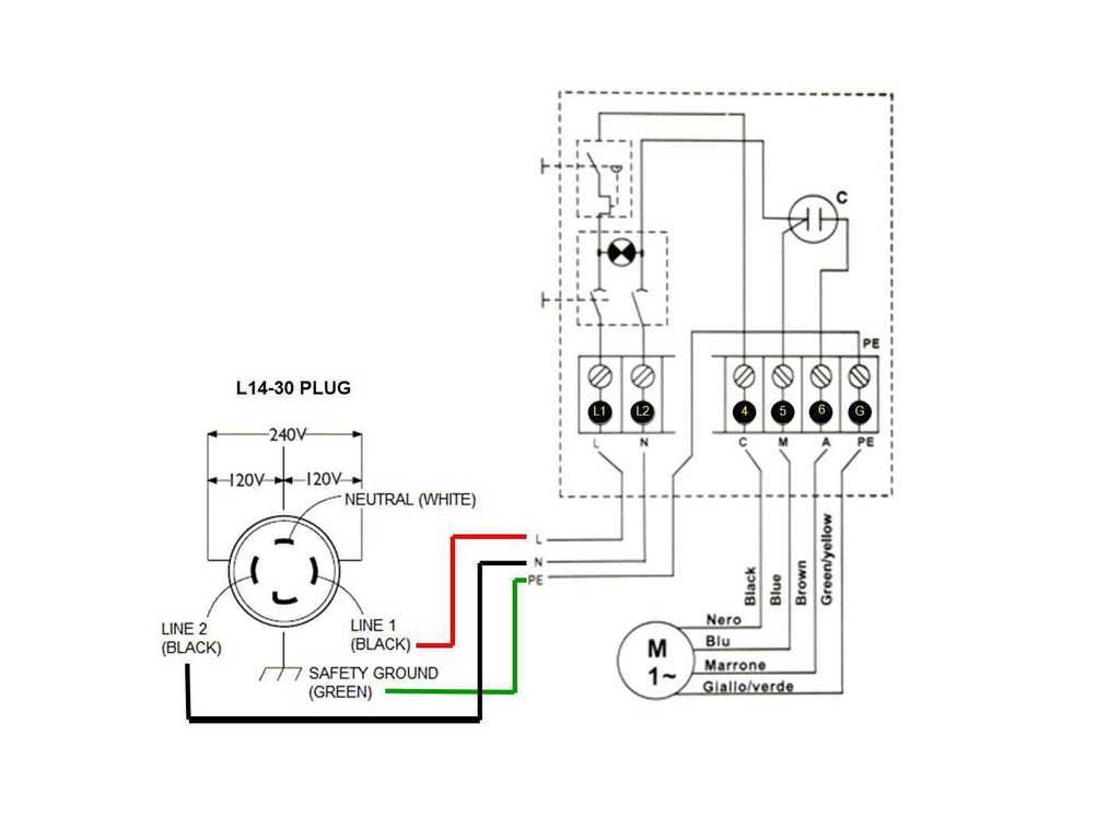
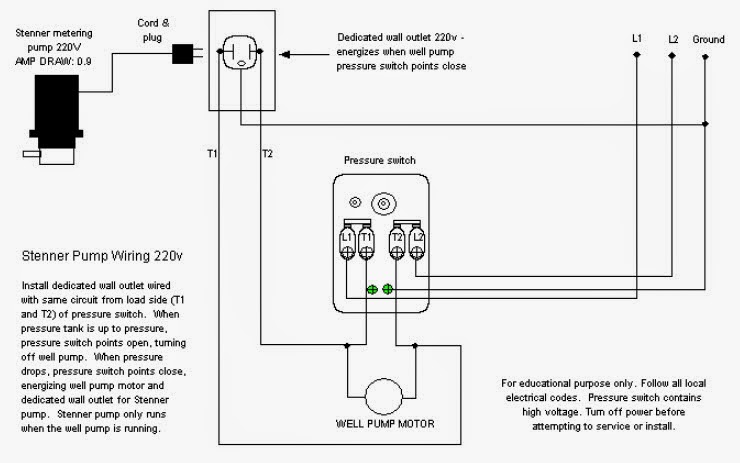
Water well worldwide power and pump services inc. A 2 wire 240v well pump may have the following wires present and connected as given at the control box.
Wiring Diagram For Livewell Pumps And Bilge Pump Page 1
Well wiring diagram. Wiring a water well pump controller and switch sta rite industries. A wiring diagram usually offers info concerning the relative placement as well as plan of tools and terminals on the devices to help in building or servicing the tool. It shows the components of the circuit as streamlined shapes and also the power and also signal links in between the devices. Owners manual shallow well jet pumpstank systems make my own house. G ground from electrical system ground to well pump circuit. In most cases if the leads are the same color then the polarity does not matter but check this with the installation sheet and wiring diagram.
A wiring diagram is a simplified traditional pictorial representation of an electric circuit. Many well drillers are not licensed and finding a licensed electrician can add unnecessary time and costs to the job. Typical 2 wire 240v well pump wiring connections. It shows the parts of the circuit as simplified forms and the power and also signal links in between the devices. All well pumps come with a wiring diagram which provide specific instructions for your specific pump. Wiring a pressure switch is simply breaking the circuit power through the pressure switch contacts.
Some knowledge of basic electronics and the ability to read simple wiring diagrams is needed but with proper research and a little practice the average do it yourselfer can develop basic wiring skills. A submersible pump can be either two or three wire regardless of the voltage coming from the. A wiring diagram is a streamlined traditional photographic representation of an electrical circuit. Wiring a water well pump controller and switch. Goulds control box for 3 wire 15hp. To wire up a pump in a water well is a relatively small project you can do yourself assuming you are the homeowner and local codes allow for this.
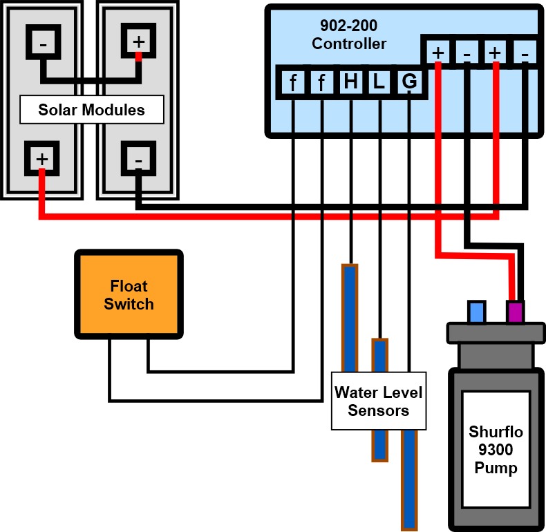
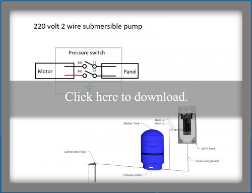
Variety of 4 wire well pump wiring diagram. 3 wire well pump wiring diagram welcome to my website this article will discuss concerning 3 wire well pump wiring diagram. M2 motor 2 to pump motor. Collection of 3 wire submersible pump wiring diagram. L1 line 1 from power source. M1 motor 1 to pump motor.
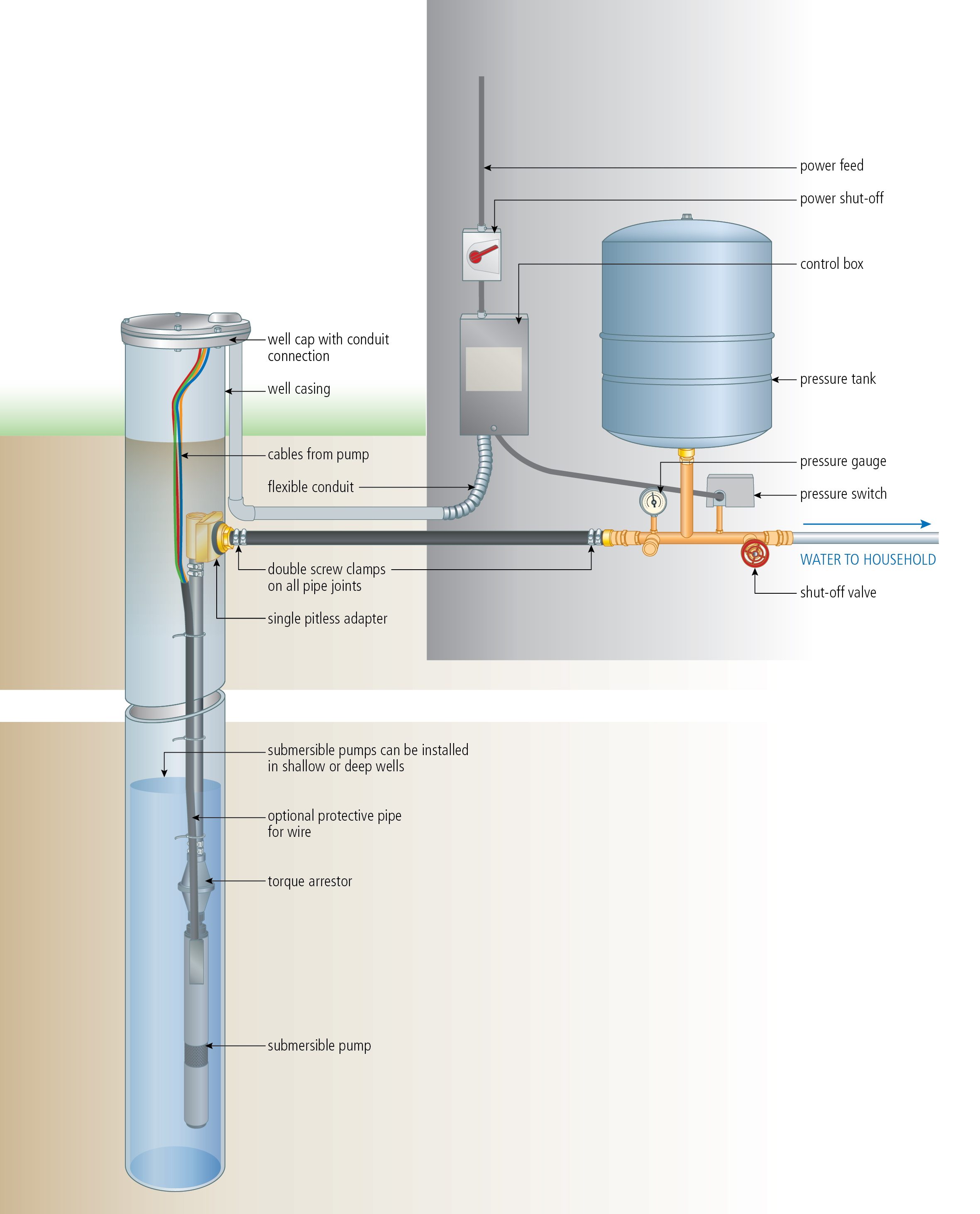
The main breaker panel should have a wiring schedule handwritten inside the front door panel. Submersible well pump wiring diagrams start at the breaker panel. It shows the elements of the circuit as simplified forms and also the power as well as signal links between the devices. We have accumulated numerous photos hopefully this picture serves for you and also assist you in locating the answer you are searching for. Squared pressure switch wiring diagram. L2 line 2 from power source.
Determine number of wires. A wiring diagram is a streamlined standard photographic representation of an electric circuit. Strip the red wire from the well or pump in the same manner and place it under the second terminal screw.
Gallery of Well Wiring Diagram