Wheel horse ignition switch wiring diagram wheel horse ignition switch wiring diagram every electrical arrangement is made up of various different pieces. Wheel horse ignition switch wiring diagram youll need an extensive skilled and easy to know wiring diagram.

De 9410 Wheel Horse Ignition Switch Wiring Diagram Schematic
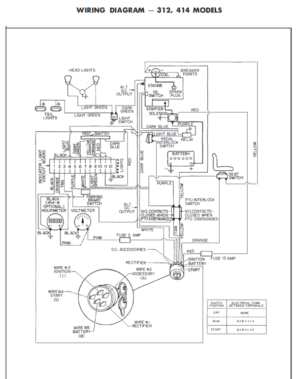
Wheel horse ignition switch wiring diagram. This applies to all old cub cadet ford jacobsen john deere wheel horse case and simplicity garden tractorsnbsp. Wiring diagram headlights i ltgrn ltgrn test switch. These instructions will likely be easy to grasp and implement. Wheel horse ignition switch wiring diagram wiring library wheel horse ignition switch wiring diagram. Tmeter pk wire 3 ignition ii wire 4 start is wire 5 battery ib pk alt ac output dkgrn light switch dkslu 0 oj. Breaker points rl red ltblu pedal relay.
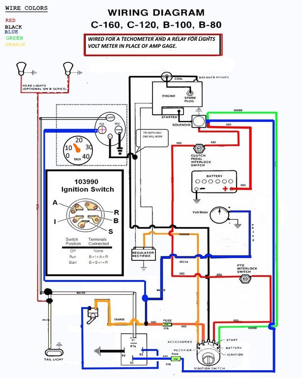
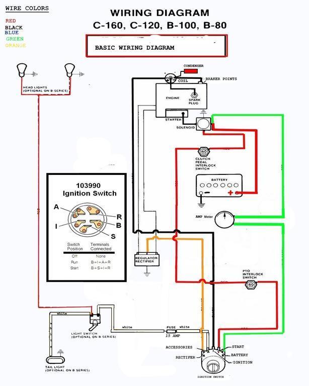
X q w s. 0 0 blk r parking blk brake 746 switch 1 optional hourmeter ljol. We did our best to keep this as simple and as easy to understand as possible. Here is a basic wiring diagram that applies to all vintage and antique lawn and garden tractors using a stator charging system and a battery ignition system. Each component should be set and linked to other parts in particular manner. Wiring diagram arrives with numerous easy to follow wiring diagram instructions.
It really is meant to help all of the average user in developing a correct program. Otherwise the structure will not function as it should be. Since the switch you have is not the one shown in the wiring diagram and the wiring has been tampered with we will need to develop our own diagram. With this sort of an illustrative guidebook you will have the ability to troubleshoot prevent and complete your assignments with ease. Using a 12 volt test light or a volt meter set for dc voltage on a range that will work for 12 volts 30 volt ground one lead and check the wires to see which one goes to the battery.
Gallery of Wheel Horse Ignition Switch Wiring Diagram