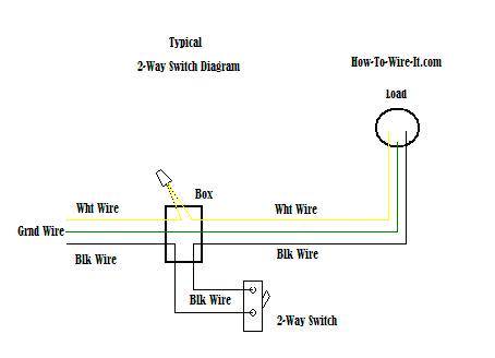
The electricity flows from the hot wire black through the 2 way switch shown in off position and then to the light and returns through the neutral wire white. This is a completed circuit.

3 Way Switch Wiring Electrical 101
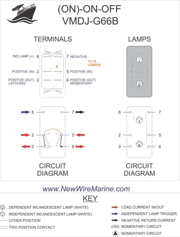
Wiring diagram with switch. This allows either engine to be started by either battery. When wiring this switch you can choose if youd like to illuminate it because of the independent lamp attached to terminals 8 and 7. Circuit electrical wiring enters the switch box the black wire power in source attaches to one of the switch screw terminals. Wiring an outlet to a switch loop. By wiring a 2 way switch the circuit below shows the basic concept of electricity flow to the load. The source is at the outlet and a switch loop is added to a new switch.
Or these terminals can be ignored for non backlit switch banks. Here a receptacle outlet is controlled with a single pole switch. Wiring a single pole light switch. Single engine two batteries. The wiring diagram to the right will show how to wire and power this 12v 20amp on off on 3 way carling contura rocker switch. From this post you complete learn about light switch wiring with a simple diagram and video tutorial in english language.
And this will be complete guide of wiring a light switch. Battery switch wiring diagrams single engine single battery diagram. The wiring of light switch is very simple connection but before we start the wiring connection. In this diagram 2 wire cable runs between sw1 and the outlet. Hey doing it yourself is great but if you are unsure of the advice given or the methods in which to job is done dont do it. Learn more about how our awesome backlit switches work here even that one is still pretty straight forward though here are some diagrams that show the single jumper required on the back of the switch.
Two engines two batteries two switches. This light switch wiring diagram page will help you to master one of the most basic do it yourself projects around your house. This site is merely. This wiring diagram illustrates adding wiring for a light switch to control an existing wall outlet. Light switch wiring diagram. 3 backlit bilge rocker switch wiring diagram.
The source is at sw1 and the hot wire is connected to one of the terminals there. Wiring a switch to a wall outlet. Explanation of wiring diagram 1 switch wiring shows the power source power in starts at the switch box. The diagram below shows the power entering the circuit at the grounded outlet box location then sending power up to the switch and a switched leg back down to the outlet. Lets assume the load you are controlling is a light. Of the three bilge pump switches the only one thats not extremely simple is the backlit automanual bilge pump switch.
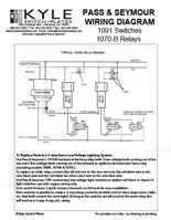
These electrical wiring diagrams show typical connections. The hot source wire is removed from the receptacle and spliced to the red wire running to the switch. This is commonly used to turn a table lamp on and off when entering a room. Port switch indicates which battery 1 all 2 is connected. Switch position indicates which battery 1 all 2 is connected to the engine.
Gallery of Wiring Diagram With Switch