Yamaha blaster stator wiring diagram encouraged in order to my personal blog in this occasion i will teach you regarding yamaha blaster stator wiring diagram. This cyclepedia manual provides repair information for 1988 2006 yamaha blaster yfs200 atvs.
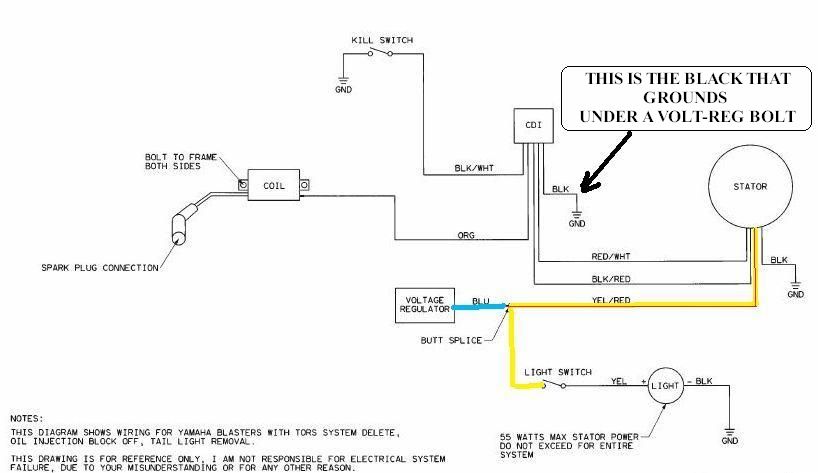
Diagram Based Yamaha Blaster Wiring Problem Completed
Yamaha blaster wiring diagram. Since youre throwing out the carb cap tors head and throttle cable youll need to replace with ims kickup pegs ims 4 gal tank wire. Alternatively the bike might be mapped too rich. 2002 yamaha blaster wiring diagram. The obvious thing is the low price as always combined with our 1 year warranty. Yamaha machine has a basic understanding of the mechanical ideas and the procedures of machine repair. I have done everything on this post and it still wont run.
Page 3 of 3 prev 1 2 3. This service manual features detailed full color photographs and wiring diagrams complete specifications with step by step procedures performed and written by a seasoned yamaha atv dealer trained technician. Another thing you will discover a circuit diagram would be traces. There is an industry standard set of wire codes in general use by most manufacturers except yamaha. There are just two things which are going to be found in any yamaha blaster wiring diagram. The throttle override system used on yamahas all terrain vehicles isnt specific the wires from the throttle position switch to the tors black box control unit.
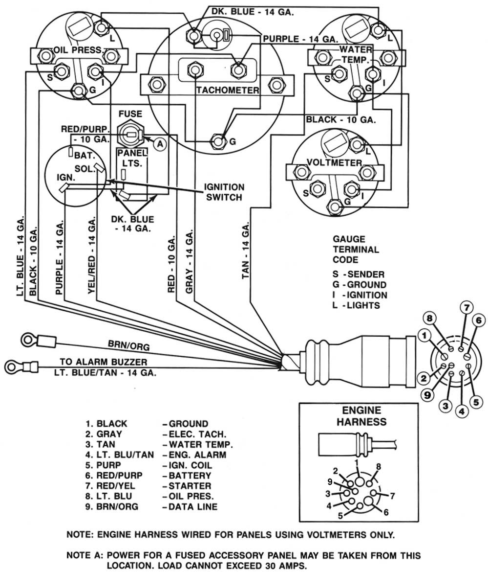
Discussion in engine started by j4m1e333 oct 21 2009. Colors listed here may vary with year model but in general should be a good guide when tracing yamaha wiring troubles. Find great deals on ebay for yamaha blaster wiring in electrical components. Mar 24 2013 messages. Yamaha blaster tors system wiring diagram. The first element is emblem that indicate electrical component from the circuit.
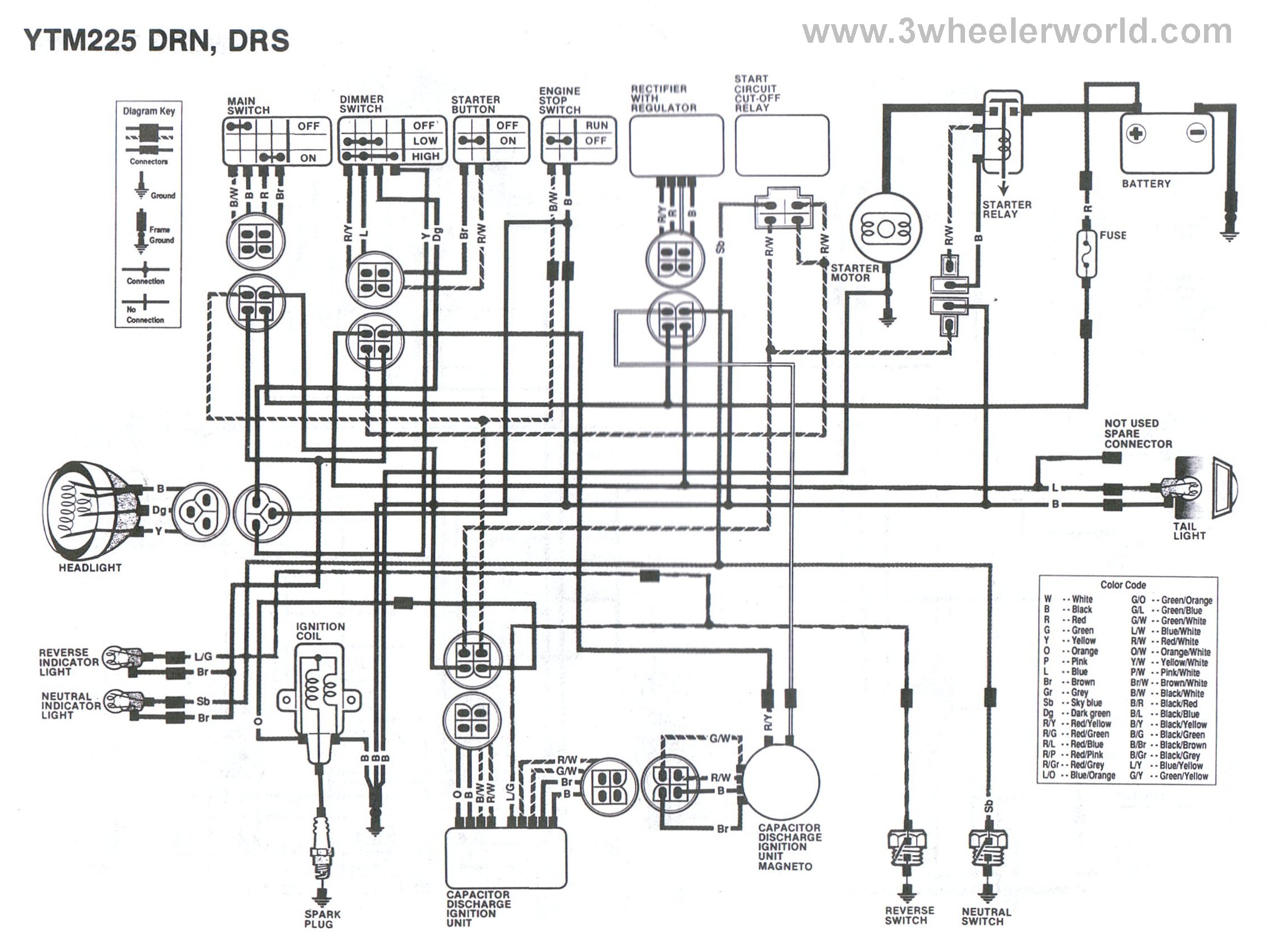
I have unplugged all tors pluggs and grounded the greenyellow wire to the frame. Yfs200p 2002 wiring diagram yfs200p 2002 wiring diagram 1 cdi magneto 2 voltage regulator 3 cdi unit 4 ignition coil 5 spark plug 6 control unit 7 throttle switch 8 carburetor switch 9 oil indicator light 0 oil level gauge a main switch b engine stop switch c lights switch d headlight e tailbrake light. Here is a listing of common color codes for yamaha outboard motors. Repairs attempted by anyone without this knowledge are likely to render the machine unsafe and unfit for use. A circuit is generally composed by numerous components.
Gallery of Yamaha Blaster Wiring Diagram