Seeking info about hitachi alternator conversion wiring diagram. You are right here.
Internal Regulated Alternator Conversion
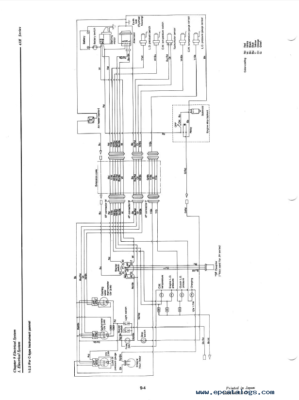
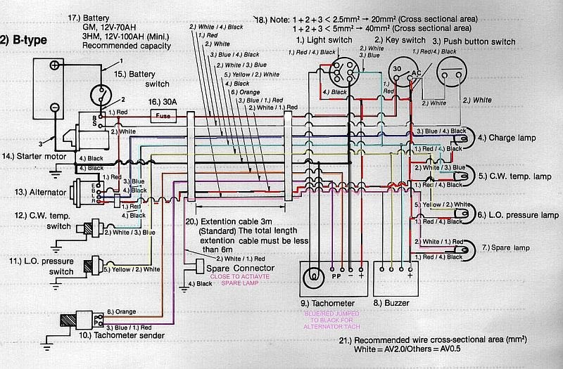
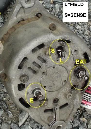
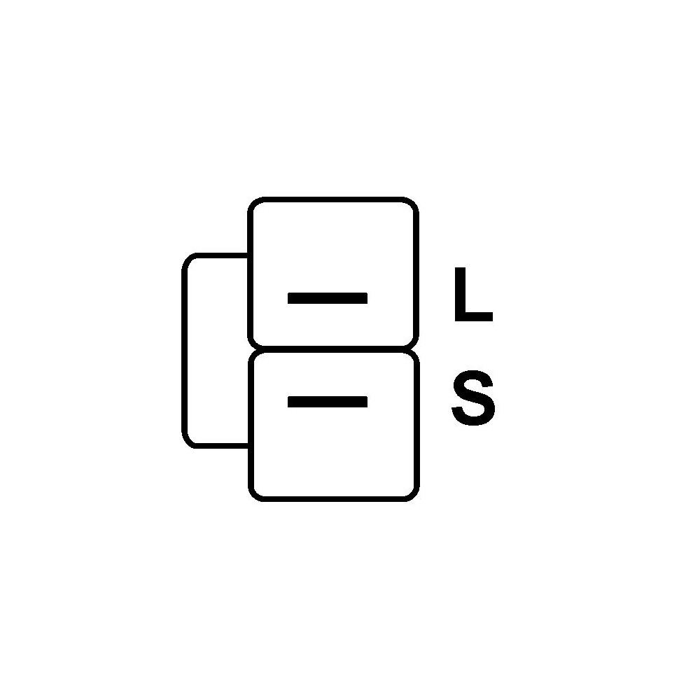
Yanmar hitachi alternator wiring diagram. Yanmar alternator wiring diagram wiring diagram is a simplified satisfactory pictorial representation of an electrical circuit. The first connects to the wire that goes to the battery and starter motor the second to the ignition and warning lights while the third if applicable is the ground wire terminal. You could be a service technician who intends to try to find recommendations or resolve existing problems. Or you are a trainee or perhaps even you that simply wish to know concerning hitachi alternator conversion wiring diagram. It shows the components of the circuit as simplified shapes and the gift and signal links amid the devices. The 2 small wires shown on the back of the hitachi alternator appear to be related to warning lights rather than switched voltage.
A saddle mount alternator such as the 315 style may also be used in many single foot applications with careful use of spacers. The alternator diagram in the yanmar gm manual does show the b terminal internally connected to the r terminal then to the regulator. Initial exitation of the alternator would therefore seem to be independent of the lamp whose only function is to confirm that a charging voltage is present edit all as in post above. Nissandiesel forums view topic. I have the wiring diagram but i cant see anything that looks like switched 12v coming through the harness. If it doesnt have a third terminal it means the alternator is grounded directly to the yanmar engine block.
The popularity of the yanmar marine engines is so vast that it makes sense for aftermarket performance alternator builders to produce a model that specifically fits yanmar engines.
Gallery of Yanmar Hitachi Alternator Wiring Diagram