Hitachi wj 200 vfd inverter wiring diagram wparameters 2 wire page 13. Igp703 installation guide for p7 drives purpose.
Vs 616g5 Series Revision F Installation Amp Quick Start
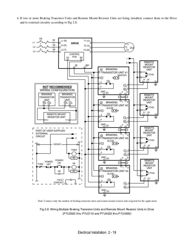
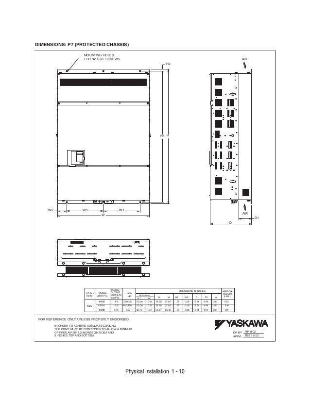
Yaskawa p7 wiring diagram. Installation guide for p7 drive wiring. This document describes wiring terminals main circuit terminal connections and main circuit terminal wiring specifications for the standard p7 drive. Yaskawa v74x vfd inverter parameters no enclosure page 11. The companion manual for advanced programming of the p7 drive is tmp702. Yaskawas p7 fan and pump drive is used for variable torque applications and is available in models ranging from 5 500 hp. Installation and user instructions for the p7 drive models cimr p7u.
For installation wire size use the data in igp703 instead of that in chapter 2 of tmp701. The p7 is thoroughly tested at the factory. Installation guide and diagram. Clear all personnel from the drive motor and machine. Yaskawa v 1000 vfd inverter wiring diagram wparameters no enclosure page 12. The equipment may start unexpectedly upon application of power.
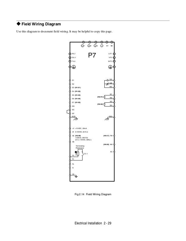
The contents of this document are included in the p7 user manual tmp701. Drive or a yaskawa office immediately. Page 57 field wiring diagram use this diagram to document field wiring. Data subject to change without notice. Warnings ii some drawings in this manual may be shown with protective covers or shields removed to describe details. E7 f7 g7 p7 iqpump ring kit attachment.
These must be replaced before operation. Observe electrostatic discharge procedures when handling circuit cards to prevent esd damage. Yaskawa electric america inc. Yaskawa p7 vfd inverter wiring diagram wparameters no enclosure page 10. It may be helpful to copy this page. Any damages or shortages evident when the equipment is received must be reported immediately to the commercial carrier that transported the material.
Gallery of Yaskawa P7 Wiring Diagram