The maximum load supported by the system is limited to 15 kva if there are two upss and bypass connected to tc see wiring diagrams below. Ul listed csa certified.

Practical Machinist Largest Manufacturing Technology Forum
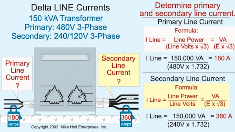
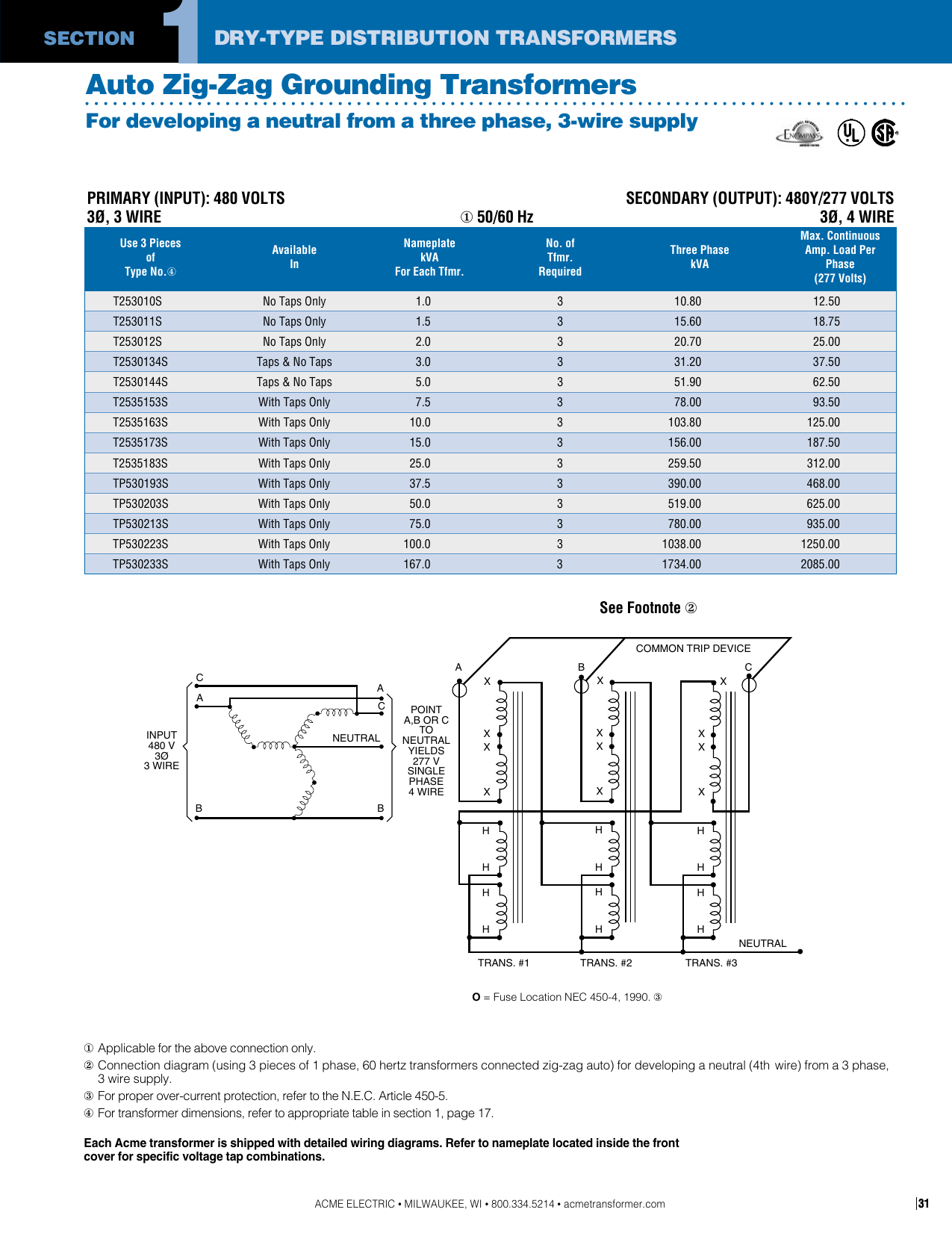
15 kva transformer wiring diagram. Ratings from 15 to 333 kva single phase and 15 to 1500 kva three phase. Amps a to kilovolt amps kva conversion calculator and how to calculate. Advantages to designing a system with low voltage transformers. Single phase kva to amps calculation formula. The wiring shall be done. Neutral x0 provided on three phase 4 wire primary volts delta transformers 15 kva through kva are equipped with a volt lighting tap.
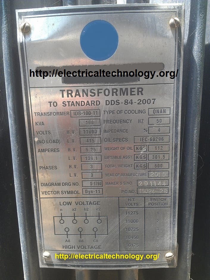
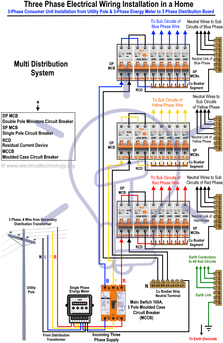
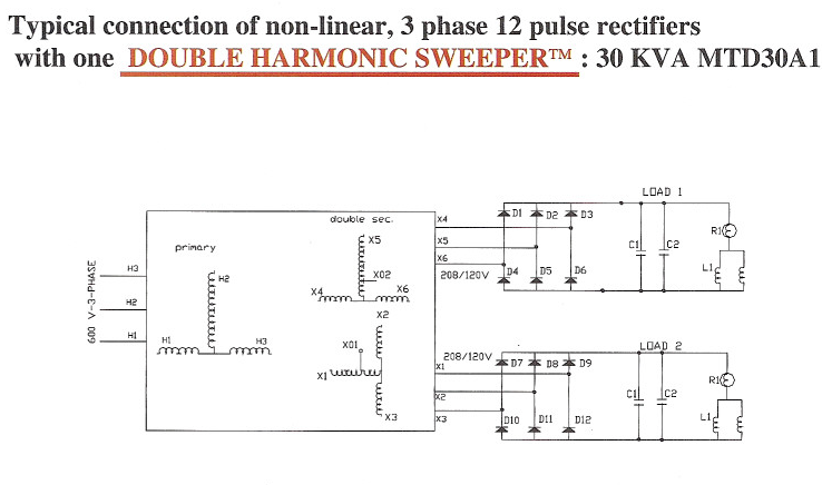
The square d distribution transformer is designed to supply power throughout the building. V 3 phase distribution panels v 3 phase distribution panels 3 phase transformer power stations 2 wheel v to v single. Terminals of the tc have two wire connection l1 and n and ground terminals. Transformer has three ratings voltage current and kva apparent power. A transformer can supply its rated kva load output to a load with a specified amount of harmonic content. An extensive standard offer complimented by a wide variety of custom products available.
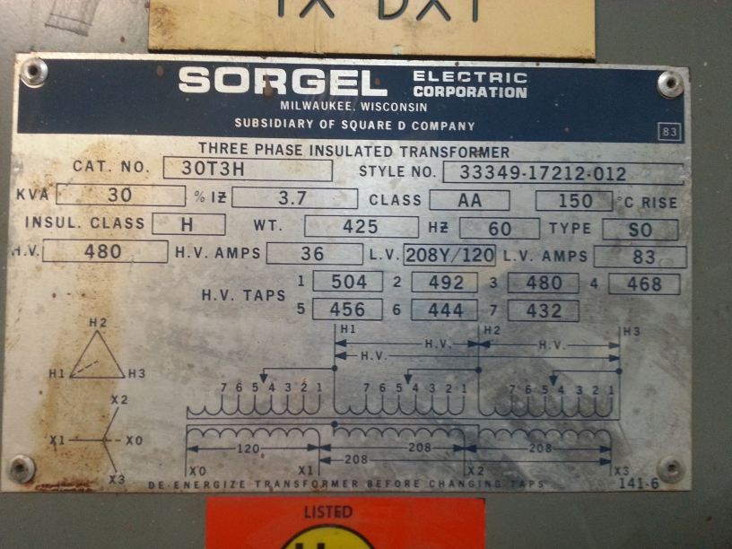
Copper and aluminum available. Ampskva calculator wiring diagram selector. Transformers 15 kva through kva are equipped with a volt lighting tap. Standard 150 deg c temperature rise and 220 deg c insulation class. 15 kva transformers three phase technical data conductor temp rise celsius electro static shield primary secondary part number k factor wiring diagram taps dimensions inches weight lbs weather shield wall mount h w d bracket al 150 y 480δ 208y t48sh2y 15 k4 k4 18 2 4 at 25 29 17125 19375 245 ws 2 wmb 3 115 t48sf2y 15 k4. Single phase transformer primary and secondary wiring.
75 10 15 n y y t all n 75 15 kva y y 240x480v 120240v p2xsf21 5 n 600v 120240v p60sf21 5 75 10 15 y. Vsecondary is the secondary voltage of the transformer and the 0. 10kv bil on all hps sentinel g product. Distributes a voltage higher than required by the load to limit wire losses and voltage drop. Three phase connection diagrams. Input output control transformer wiring mystery.
The transformer permits multiple voltages to be leveraged in the design of the system. The upper ground terminal is for a load cable and the lower ground terminal is for upss. Product connect a jumper between the h2 and h3 terminals and bring the v in on h1 h4. 15t2f transformer dry 3ph 15kva 480v 208y120v. Supply 440v 3 ph taking 1 phase 240v and steping down to 110v single phase. Using the same turns ratio of the above transformer 21 calculate the following.
Gallery of 15 Kva Transformer Wiring Diagram