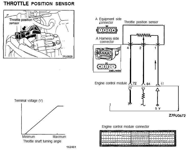
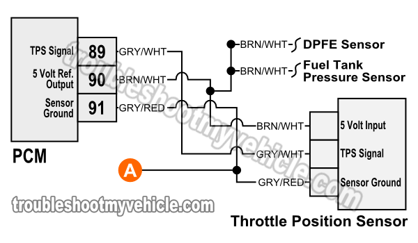
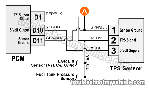
Throttle position sensor tps wiring diagram 1997 1998 ford 46l 54l. 475 to 525 vdc.
Timing And Tps Questions Bronco Zone
Accelerator pedal position sensor wiring diagram. I need the wire diagram for the peterbilt side of the throttle position sensor. The unit had a brake in the original oem harness to the ecm. Accelerator position sensor aps the ecm sends a regulated 5v signal through the ecm black chassis connector terminal 3 to aps connector terminal c. The o2 wiring was frayed and fried the ecu circuitry which controls it. Turn key switch on and connect diagnostic tool. Accelerator pedal position sensor wiring diagram wiring diagram is a simplified satisfactory pictorial representation of an electrical circuit.
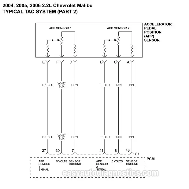
The gryred wire feeds ground. Now i have code 00777 accelerator position sensor g79 27 10 implausible signal intermittent. Get the details on testing the app. I just got through resolving code p0134 o2 sensor sensor circuit no activity on a 2000 jetta vr6. It receives two reference voltages from the powertrain control module pcm having two ground wires and two signal wires that send a varying voltage back to the pcm relating to accelerator pedal position. Replacing the o2 sensor along with the ecu eliminated the code.
The grywht wire carries the tp signal to the pcm. Yes go to 2c no go to 3a step 2c turn keyswitch off and disconnect the accelerator pedal position sensor from the oem harness. Wire colors a red with org trace blue and black with white trace. The accelerator pedal position sensor is inside the accelerator pedal assembly. A pete dealer by passed the harness and went straight to the ecm. F150 f250 f350 crown victoria e150 e250 e350.
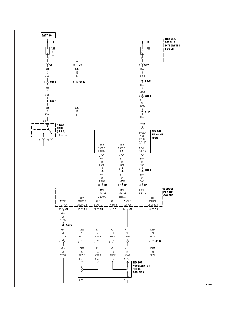
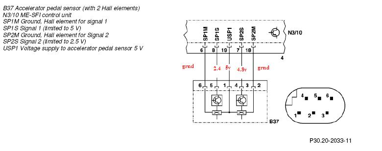
Mounted on the accelerator pedal. Accelerator pedal position sensor 5 volt supply pin to the accelerator pedal position sensor return pin at the sensor connector of the oem harness. The accelerator pedal assembly is serviceable to the extent that the apsivs switch can be replaced without replacing the complete assembly. Each one has separate signal ground and 50 volt reference circuits. It shows the components of the circuit as simplified shapes and the skill and signal links amongst the devices. In doing so they removed the pins from the 3 pin connector on the floor.
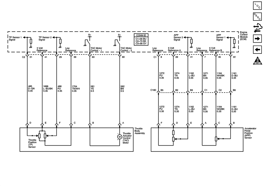
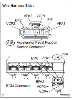
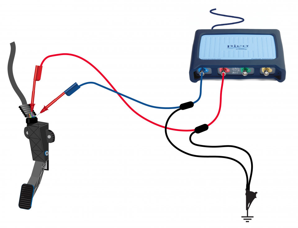
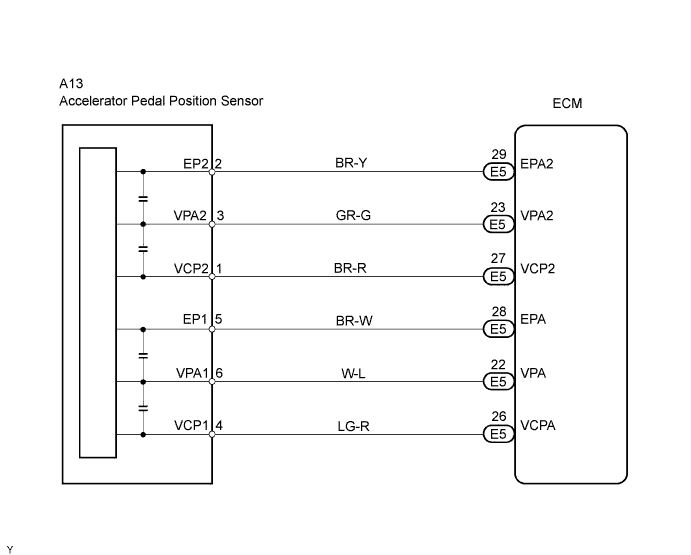
The accelerator pedal position sensor is mounted on the accelerator pedal to detect how much it is de pressed. The accelerator pedal assembly is not connected to the throttle plate via a cable like in the good ole days. It has 2 sensor terminals vpa and vpa2 to detect the accelerator pedal position and a malfunction. Wiring diagram inspection procedure 1 read value of handheld testeraccel pos 1 and 2 a connect the handheld tester to. In this example the accelerator pedal position app sensor is of the potentiometer type. In many ways the app or accelerator position sensor is a dual tps connected to the gas pedal.
There are variations on testing the app as opposed to a simple tps. Brnwht wires feeds the tps 5 volts dc. That the accelerator pedal assembly is made up of 3 individual position sensors.
Gallery of Accelerator Pedal Position Sensor Wiring Diagram