Faq wiring diagram combination boiler st9120 t6 and t4 additional wiring diagrams 04 20 v4043 zone valve s plan operation. Wiring diagrams for oil burning and water boilers are noted.

Thermost Wiring Ac Service Tech
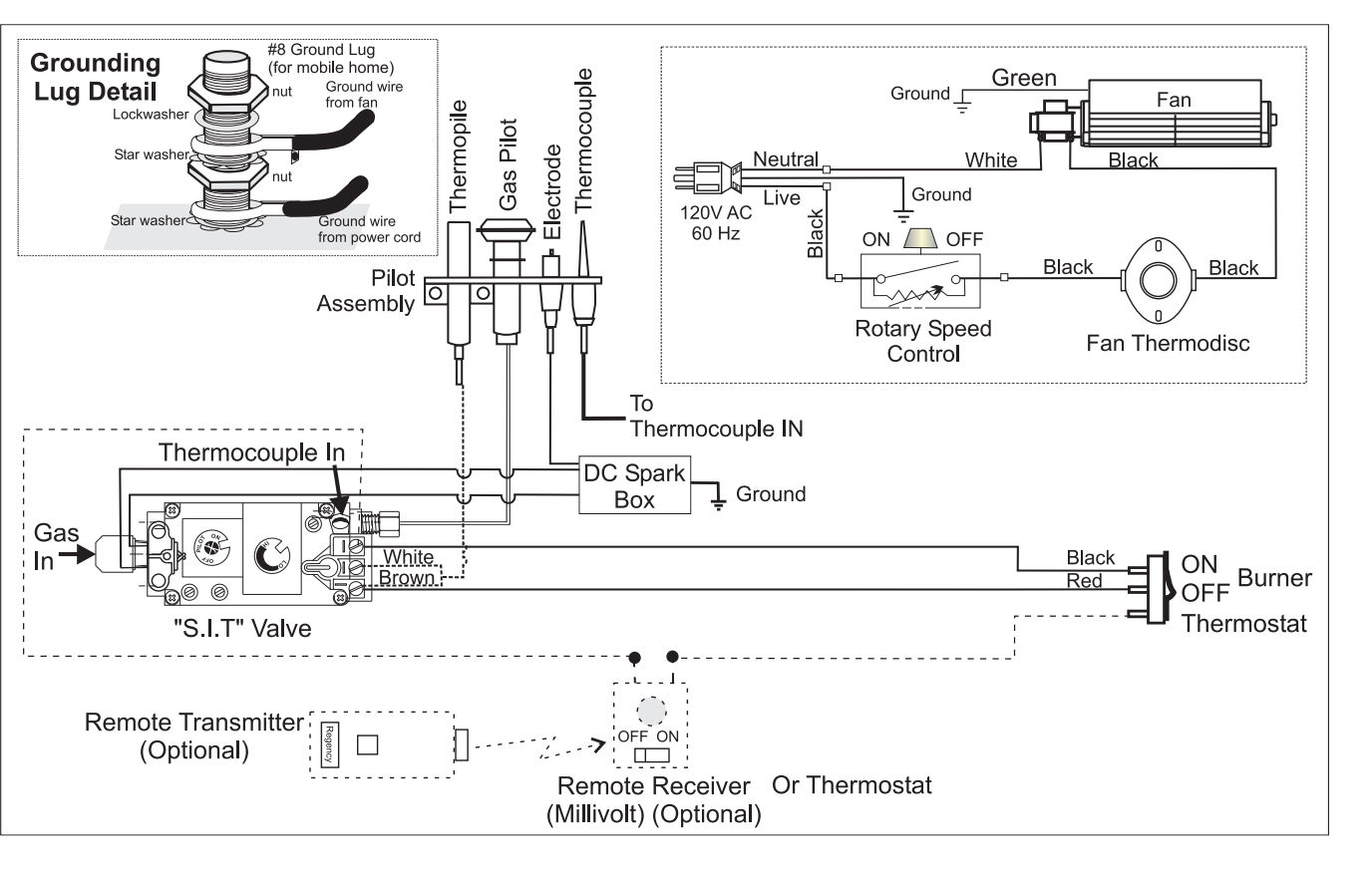
Back boiler wiring diagram. Note y2 some ac systems will have a blue wire with a pink stripe in place of the yellow or y wire. 1 inch on sidesback and 6 inches on front of boiler does not supersede clearance to combustible materials. A wiring diagram is a streamlined standard pictorial depiction of an electric circuit. More in boiler stoves key building regulations. This wiring diagram shows 120 v coming from l1 of a circuit breaker through a switch powering a boiler control and returning through l2 back to the neutral bar of the circuit breaker box. Ive no experience of back boiler wiring and its components could anyone please explain what back boiler wiring consists of or any circuit wiring diagrams.
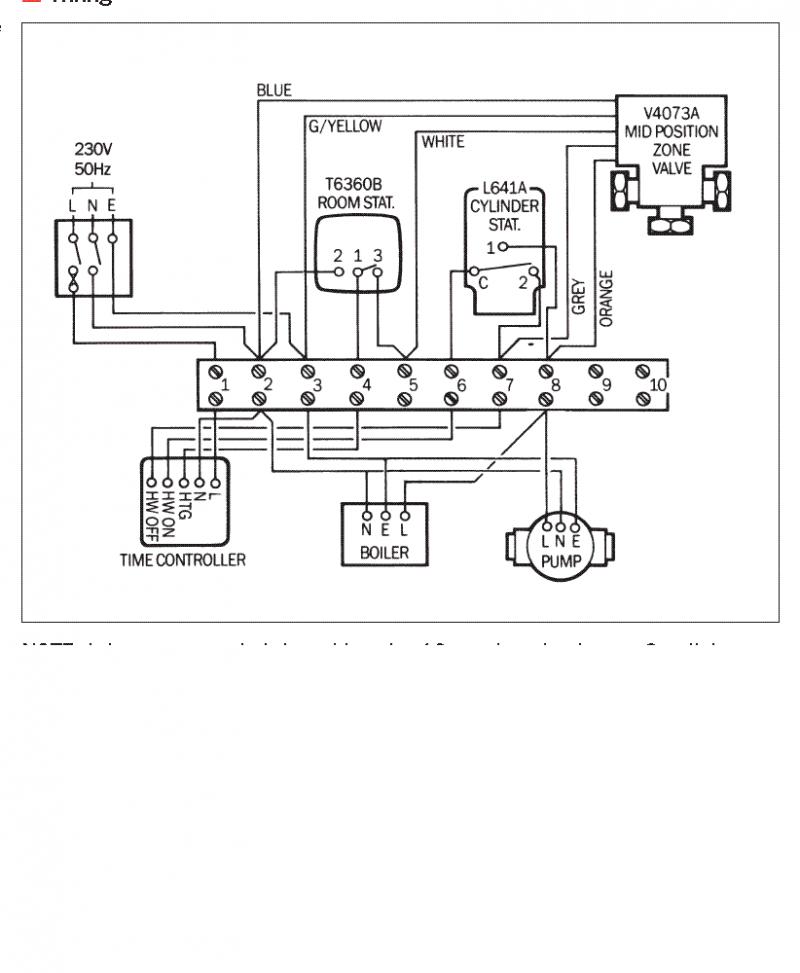
Hrt 20 and 30 boiler wiring diagram. Our wiring diagrams section details a selection of key wiring diagrams focused around typical sundial s and y plans. This is fine if the boiler is 120 v. If you are looking for this on my diagrams above it is the pipe that b is strapped to. I am carrying out a rewire shortly and been advised the heating system is a back boiler system. The trailer wiring diagram shows this wire going to all the lights and brakes.
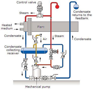
Also it must connect with things if included that use the aux power and back up lights too. However most gas boilers you will be working on have 24 v controls. Refer to the blower chart for cfm requirements. Some trailer builders just connect this wire to the frame then connect the ground from all the other lights and accessories to the frame as well. Variety of central boiler thermostat wiring diagram. The pipe leaving the top of your coil usually 22mm should rise slightly between cylinder and where it meets the primary circuit so air is not trapped at the top of your coil.
Refer to national fuel gas code for additional requirements for louvers grilles screens and. Always refer to your thermostat or equipment installation guides to verify proper wiring. Ct 6 and 25 boiler wiring diagram. Ct 6 10 15 and 25 boiler wiring diagram. Wiring diagrams and component coding. Most of the wiring diagrams are for natural gas powered steam boilers.
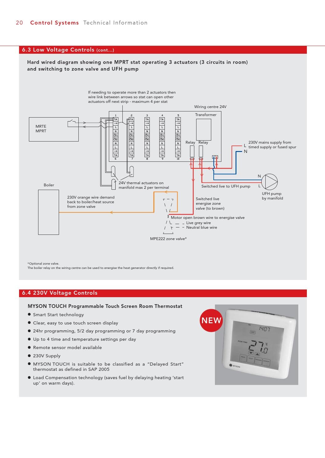
This diagram is to be used as reference for the low voltage control wiring of your heating and ac system. To get from 120 v to 24 v we use a transformer. Ct 35 and 50 boiler wiring diagram. It reveals the parts of the circuit as streamlined shapes and also the power and signal links in between the tools.
Gallery of Back Boiler Wiring Diagram