It shows the elements of the circuit as streamlined forms as well as the power and signal links between the devices. Connect the brown wire to the solenoid using a different terminal.

Diagram Based Boss Plow Solenoid Wiring Diagram Completed
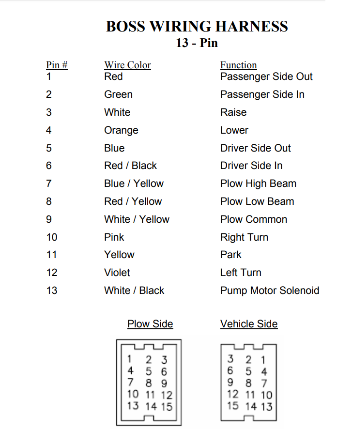
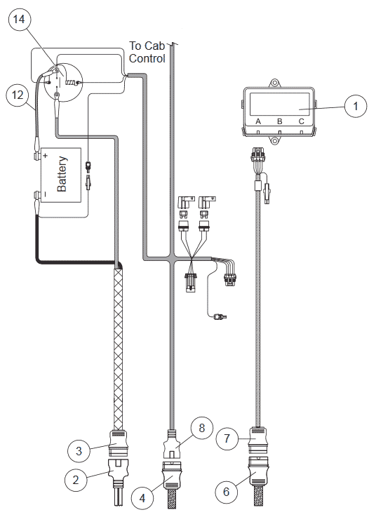
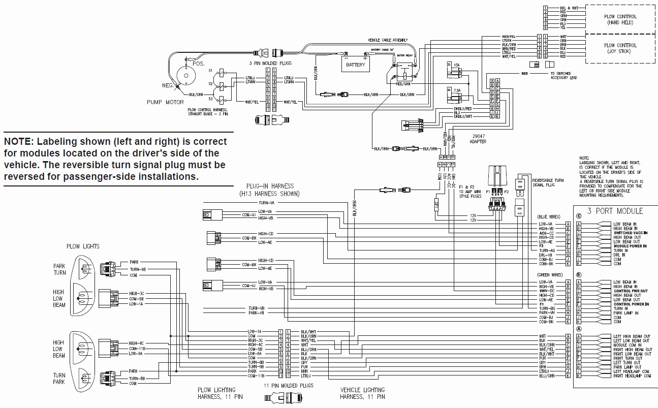
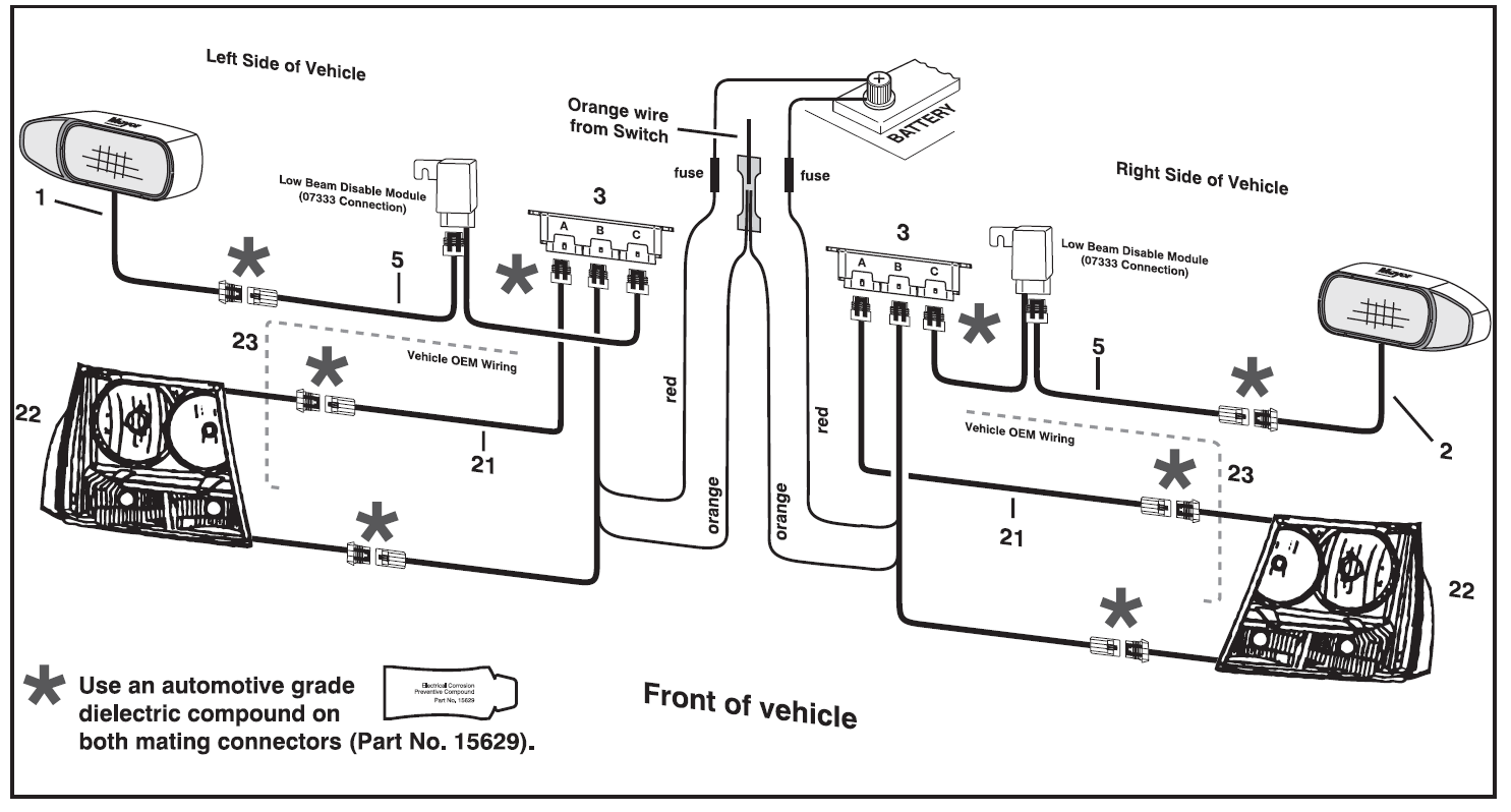
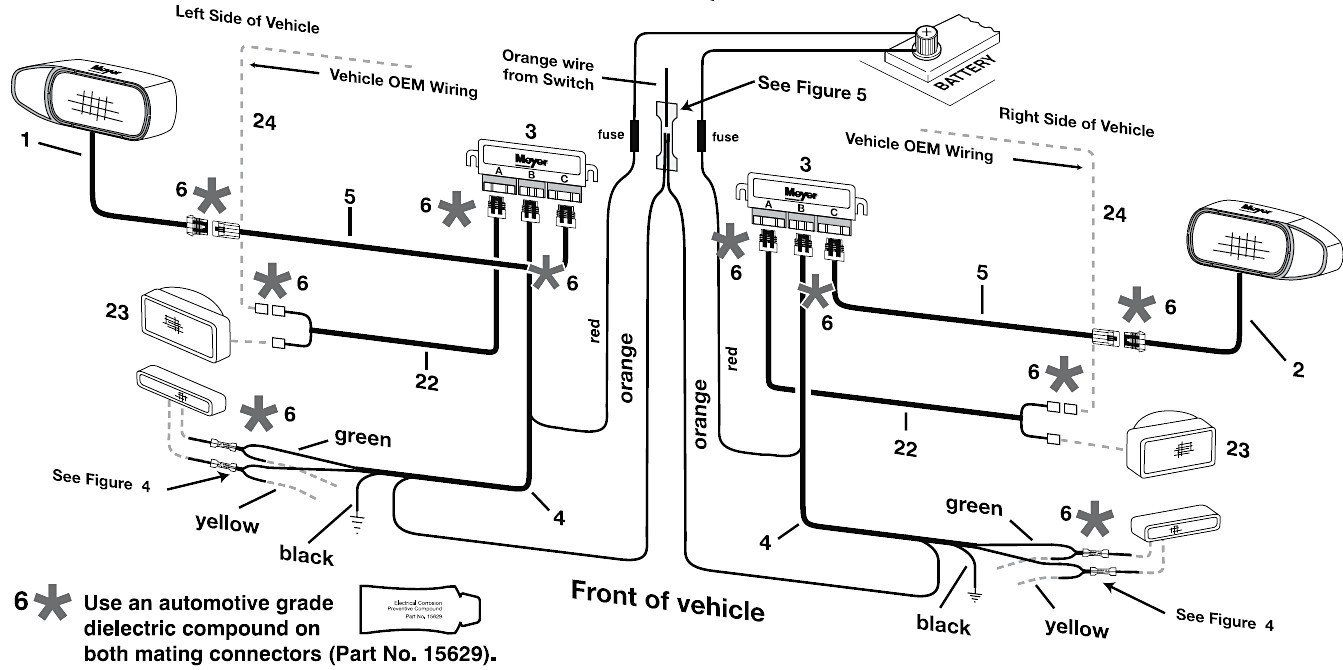
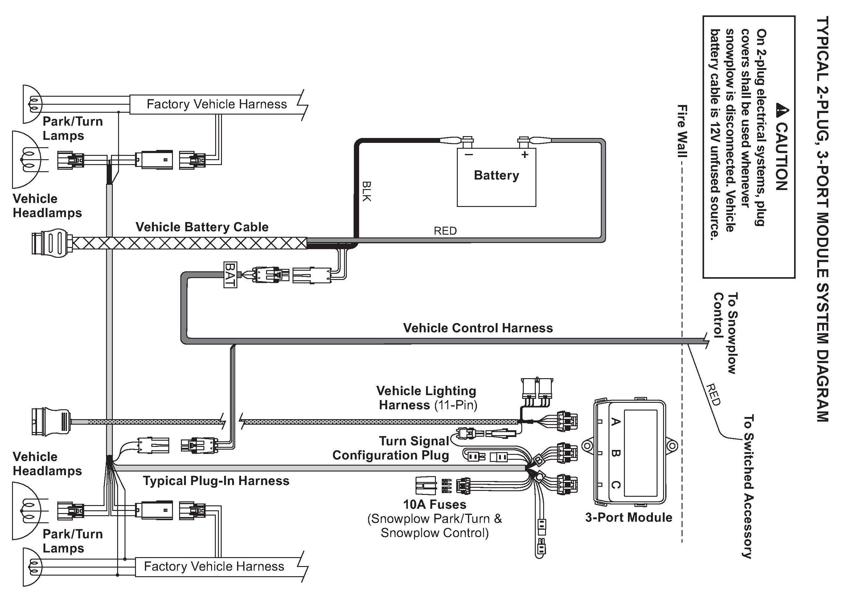
Boss v plow solenoid wiring diagram. Wiring diagram smartlight2 wiring schematic smartlight2 control plug pin functions. Rt3 wiring diagram rt3 wiring diagram. Otherwise the structure wont function as it should be. Connect the blackred wire to the keyed 12 v power supply and the whiteblack wire to the small terminal on the pump solenoid. Connect the two tab connectors to the headlight toggle switch then plug the 9 pin molex connector into the controller. A wiring diagram normally gives info regarding the relative placement and plan of gadgets as well as terminals on the gadgets to assist in structure or servicing the device.
A wiring diagram is a simplified standard photographic depiction of an electrical circuit. Intercon truck equipment 1200 pauls lane joppa md 21085 tel. Boss plow wiring diagram boss plow solenoid wiring diagram boss plow wiring diagram boss plow wiring diagram plow side every electric structure consists of various distinct components. Each component should be placed and linked to different parts in particular manner. Collection of boss v plow wiring diagram.
Gallery of Boss V Plow Solenoid Wiring Diagram