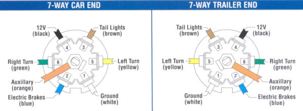
If you are looking at the inside of the trailer connector where the wires mount to the terminals starting at the top and rotating clockwise. 4 pin trailer wiring diagram.
Home
Cm trailer wiring diagram. Cm trailers offers over 25 years of experience in manufacturing robust steel and all aluminum trailers that you can. Cm trailers are designed to meet the needs of any rural lifestyle from the weekend trail rider to professional livestock haulers and showmen. Complete with a color coded trailer wiring diagram for each plug type this guide walks through various trailer wiring installation solution including custom wiring splice in wiring and replacement wiring. June 8 2018 april 12 2020. Use on a small motorcycle trailer snowmobile trailer or utility trailer. The below information is for reference and is commonly used throughout the industry but can vary depending on who built the trailer.
We even offer a full line of cargo trailers. Cm trailer equipment are a leading distributor of high quality trailer parts and components to the light trailer building industry in new zealand. Extrapolate the same expansion for additional axles. Above we have describes the main types of trailer wiring diagrams. 34 inch by 1 inch 6 way rectangle connectors right turn signal green left turn signal yellow taillight brown ground white. Cm trailer wiring diagrampage2 toyota tacoma trailer wiring diagram.
The red and blue wire can be used for brake control or auxiliary. These 2 wire diagrams fit the needs for most trailers. You can be assured that we have the right parts to suit your requirements phone. So go on ride along with a cm trailer. Can also be used as custom wiring on trailers with 3 lightwire systems. To connect the electric system of your trailer to the vehicle you will be using special connector.
When wiring a trailer connector it is best to wire by function as wire colors can vary. If your vehicle is not equipped with a working trailer wiring harness there are a number of different solutions to provide the perfect fit for your specific vehicle. The image above shows a single axle trailer and the next image shows wiring for tandem axles. Only the blue brake and white ground wires are different. Below is the generic schematic of how the wiring goes. Check out or trailer wiring diagrams for a quick reference on trailer wiring.
We have an excellent wiring diagram on our website i will provide you a link so you can look at it. You can use a circuit tester to verify connections. Typical trailer wiring diagram and schematic. Trailer wiring diagrams trailer wiring connectors various connectors are available from four to seven pins that allow for the transfer of power for the lighting as well as auxiliary functions such as an electric trailer brake controller backup lights or a 12v power supply for a winch or interior.
Gallery of Cm Trailer Wiring Diagram