Ryb electrical 986298 views. Applications complete management of three phase refrige rating systems up to 75 hp static or ventilated.

Ecp Wiring Diagram Pt 1 24100 Ecp Plus Canadaecp Plus Canada
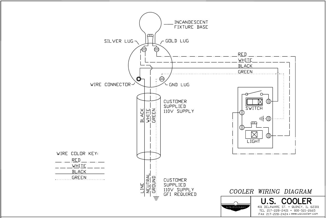
Cold room wiring diagram pdf. Freezer room electrical diagram. 33 wiring is carried out in line with manufacturers specifications and workplace procedures. T t3 compressor contactor l3 ladder diagram fan y rv rv rv coil cc c defrost control. And local codes 208230 vac 60 hz 3 ph. It includes the entire panel ceiling panel and room panel which is made from import pipeline auto perfusion foaming import black material double side pressed colored steel panel with protective coating and the thickness is generally 100 mm 120 mm and 150 mm. Ground equipment per nec.
Cold room control panel freezer room duration. Air cooled condensers outdoors need head pressure control when. Cold room ambient temperature range is 5c to 40c. Bk bl bl bl when used pri trans sec r bl g r bl t1 l1 cont. Cold room design guideline us guide. 32 contactor and circuit breakers are mounted on trays in the control box.
Required to operate in ambient temperatures below 60 f. A wiring diagram is a streamlined traditional photographic representation of an electrical circuit. Cold room designguidelines free ebook download as pdf file pdf text file txt or read book online for free. Evaporating unit only for complete cold room management. Project identification and construction signs. 31 procedures and information required for wiring cold and freezer room are obtained and source in line with workplace procedures.
Oil level is at the designed limits. Complete the wiring with the push on connectors. Front access to the automatic fuse and motor protector for the compressor and an innovative design combine to make it the ideal choice for effective refrigeration control. Variety of cold room control panel wiring diagram. Connection diagram o bl o bl attach ground ps2 ps1 lphp lphp two switch wiring r power supply per nec. It shows the elements of the circuit as streamlined shapes as well as the power and signal connections between the devices.
Three phase dol starter control overload indicator power wiring diagram duration. It shows the components of the circuit as simplified shapes and the power and signal contacts amongst the devices. Word cool not cold. On initial operation or restart after a long time the crankcase heater should be energized for 6 hours prior to start up. General components of cold rooms. Thermostat and other control units of the cold storage room are properly set.
Cold room wiring diagram pdf wiring diagram is a simplified normal pictorial representation of an electrical circuit.
Gallery of Cold Room Wiring Diagram Pdf