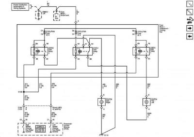
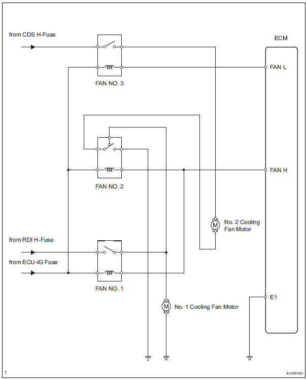
Cooling fans are now controlled by the ecm through the respective module network and using duty cycle control signals. Ceiling fan wiring diagram.
Chevrolet Corvette Questions Cooling Fan Cargurus
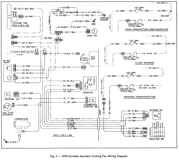
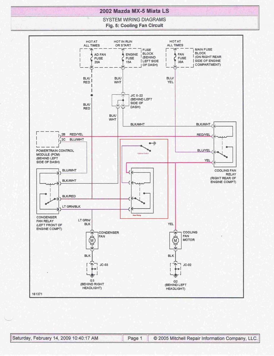
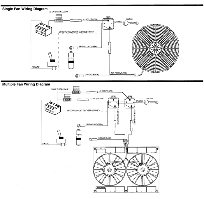
Cooling fan wiring diagram. Start with taking both of the positive wires from the fans and run it to the yellow wires on each relay. Or you are a pupil or perhaps even you who simply want to know about ford mustang cooling fan wiring diagram. Take a closer look at a ceiling fan wiring diagram. Check for battery voltage at terminal 2 of fan relay connector fig. Wiring dual cooling fans. You could be a specialist that intends to look for references or address existing troubles.
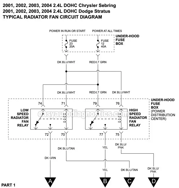
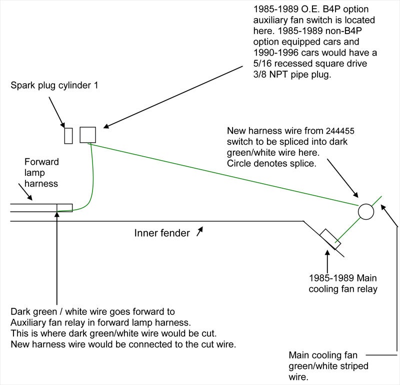
Now take the power wire from your fan and connect it to the wire that is going through the firewall. Refer to wiring diagrams for circuit diagram. This will be the wire that connects your switch to your fan power wire. Relays shown in these diagrams can provide options. Searching for information about ford mustang cooling fan wiring diagram. This is based on the draw from the fans if the fans are larger and draw more than 15 amps each its recommended to install a second relay kit as shown below.
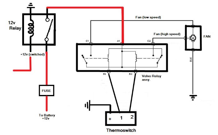
You will then need switched power usually from your ignition switch wired to the blue wires on the relays. Start your wiring project by taking both of the positive wires from the fans and run them to the yellow wires on each relay tab 87. So now we have a wire that goes through the engine bay to the cabin of your car. Httpsamznto377klrp those fans fit perfect on 68 72 gm a body cars but are not recommended for ls engine. 800 x 600 px. Just an idea on how to wire up electric cooling fans for your vehicle cooling fans.
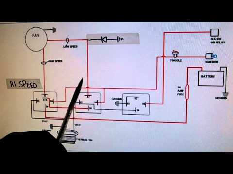
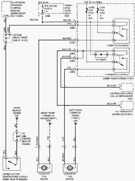
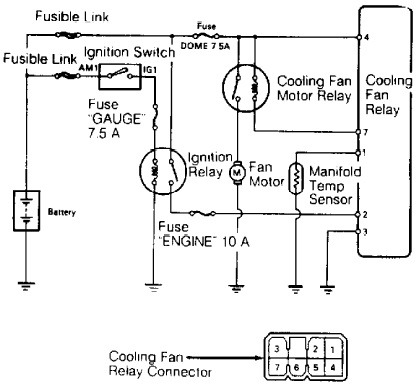
Suggested electric fan wiring diagrams suggested primary cooling fan single speed onoff using 12 volt switching devices only for primary activation note. Most stand alone adjustable thermostats ie. You are right here. Connect a jumper wire across the radiator temperature switch harness connector. This might seem intimidating but it does not have to be. Hayden flex a lite or perma cool brands can provide a 12 volt output when activated.
The color coded diagram below will correspond with the wires on the relay kit to help simplify the wiring process. Get the 10 gauge wire and place it through the hole in your fire wall. The cooling fan wiring diagram below is what weve found to be the simplest and most reliable method. With dual cooling fans there are two methods for wiring up the relay kit. With these diagrams below it will take the guess work out. Pick the diagram that is most like the scenario you are in and see if you can wire up your fan.
It uses a 40 amp electric relay and electric fan sensor. Here youll also be exposed to the current path voltage and sensor signal.
Gallery of Cooling Fan Wiring Diagram