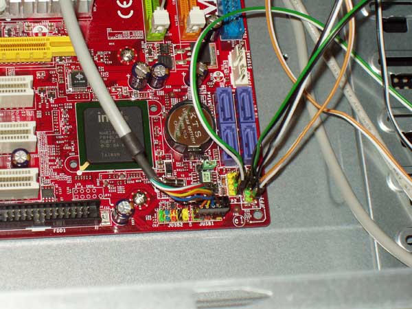
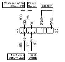
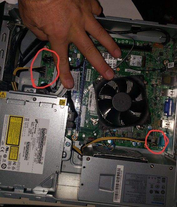
Diagram for connecting computer components this is the monitor cable connector. Your motherboard manual will have a page that shows a detailed diagram of what goes where.

Wiring Diagram Electronic Circuit Circuit Diagram Schematic
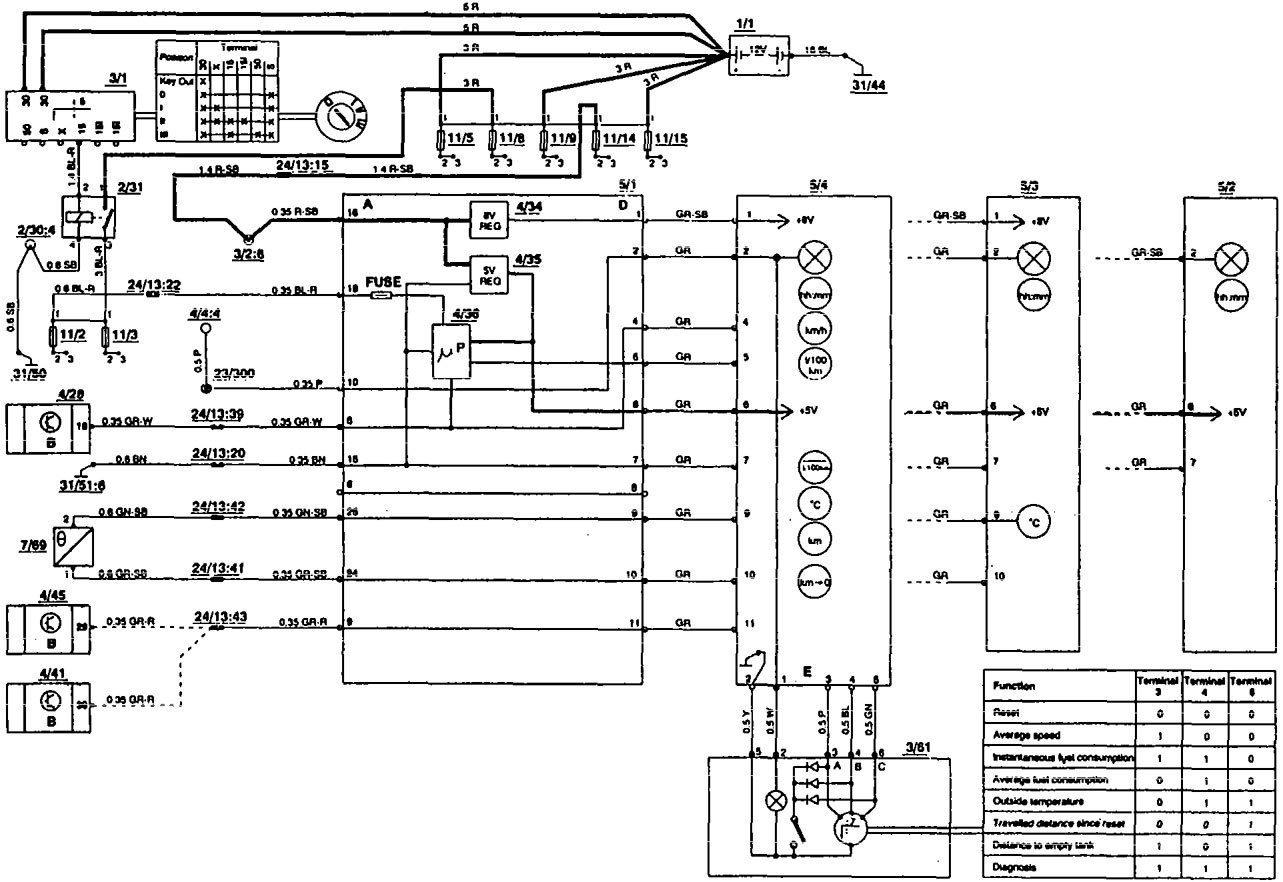
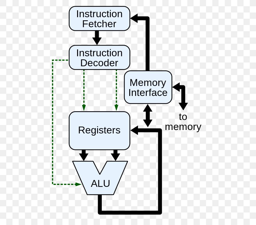
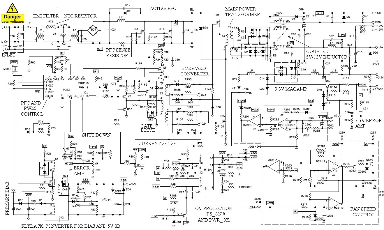
Cpu wiring diagram. Main power supply auxiliary 24vdc supply to programming device operator inputs commons commonsoutputs 24vdc out power input system dl405 interface network output module internal backplane supply for. Cpu c accepts two cpu c and cpu c accept eight signal modules. 6eshhxb0 sm wiring diagram 6esbhxb0 wiring diagram 6eshfxb0 6es7 bfxb0 6eshfxb0 datasheet 6esbhxb0 manual 6esbfxb0 datasheet datasheet in pdf download. Here are the computer connections we need to plug in. Cpu 1215c acdcrelay 6es7 215 1bg40 0xb0. The example wiring diagram below on the right shows how this can work but also that the auxiliary supply output is an unused.
Cpu 1215c wiring diagrams. For a computer connection diagram click on the picture below in order to get a closer look at the ports in which your computer components will attach. You will see things like hdd power pwr etc. Look on your motherboard for the front panel connection area. See label m on the motherboard diagram. Autozone repair guide for your wiring diagrams cpu 2001 central processing unit cpu wiring diagram a air bag supplemental restraint system 1999 air bag supplemental restraint system 2000.
Gallery of Cpu Wiring Diagram