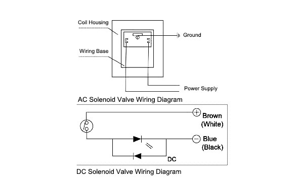
Use figure 1 if your motor has a single voltage shunt field. Use figure 2 if your motor has a dual voltage shunt field.

Wiring A Solid State Relay
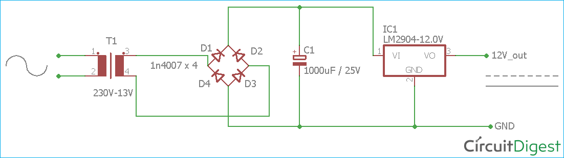
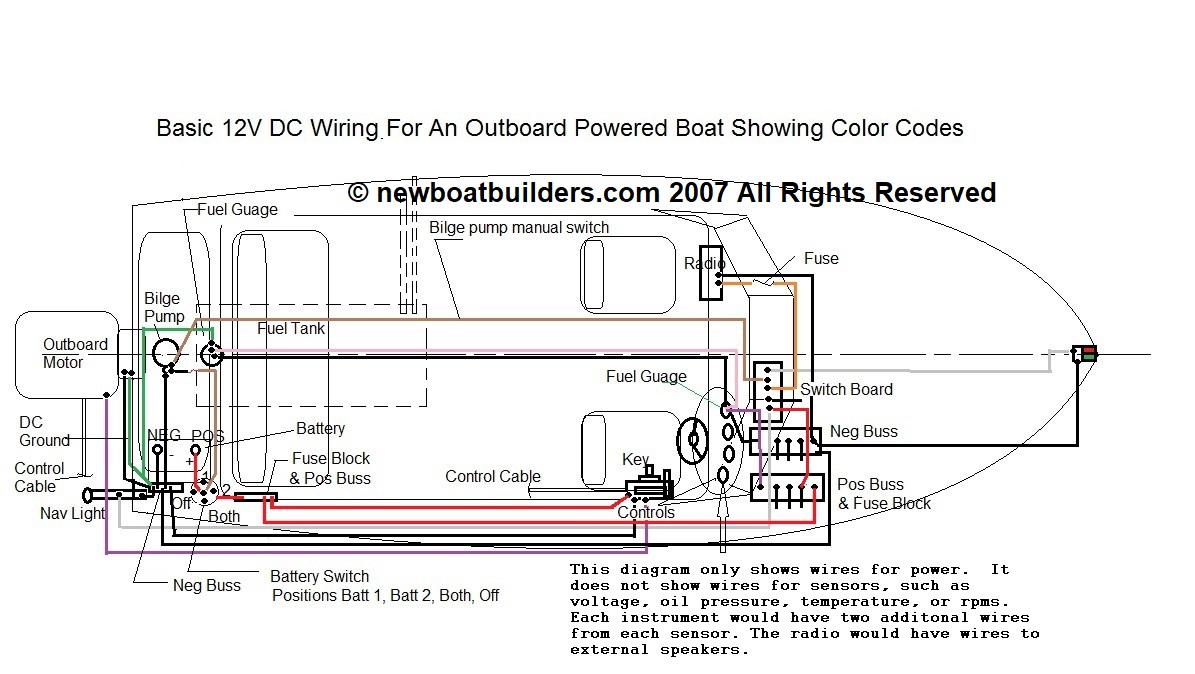
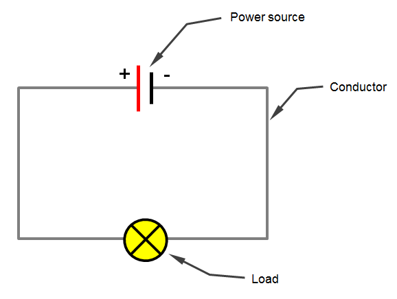
Dc wiring diagram. Wiring diagram for ac dc inc. Motor connections your motor will be internally connected according to one of the diagrams shown below. These connections are in accordance with nema mg 1 and american standards publication 06. Dcc wiring is different from dc blocks and cab control in consideration of wiring methods but many of the same basic rules for electrical gaps etc. Direct current dc electric circuits. A dc circuit is necessary for dc electricity to exist.
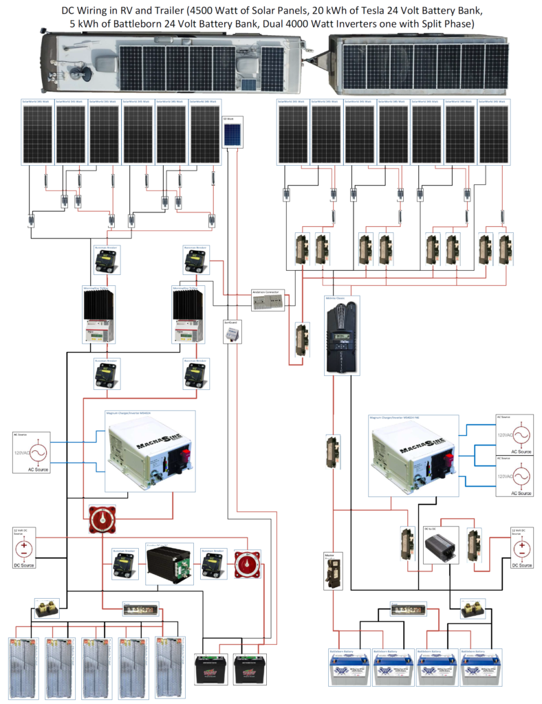
This is a good time to redraw it before starting on the ac system. By the time you get through diagramming the dc system youll have a good sense of how you want your wiring diagram to look. Motor wiring diagram dc. It should be noted that sometimes the control functions are supplied by ac and are included in the elementary diagram refer to figures 6 and 8. Panels 2016 version wiring for instrument panels with transmission pressure gauge 12 position terminal wiring diagram for ac dc inc. By ron kurtus revised 17 october 2019 a direct current dc electric circuit consists of a source of dc electricitysuch as a batterywith a conducting wire going from one of the source terminals to a set of electric devices and then back to the other terminal in a complete circuit.
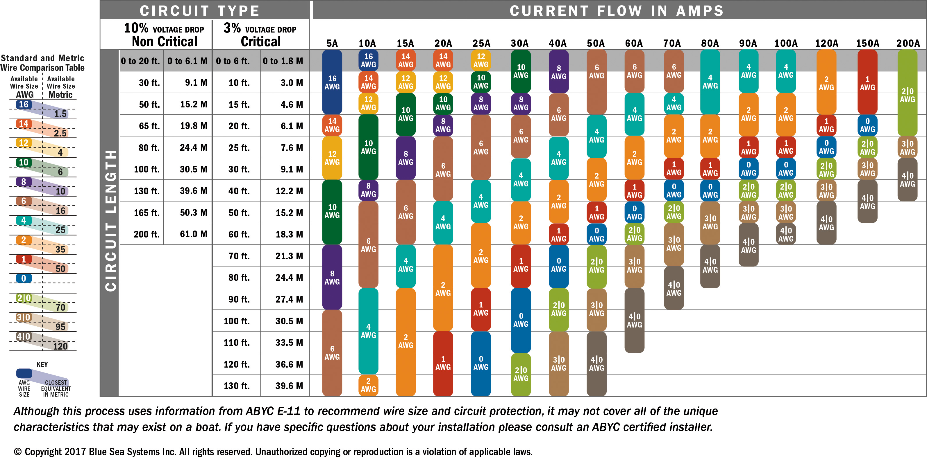
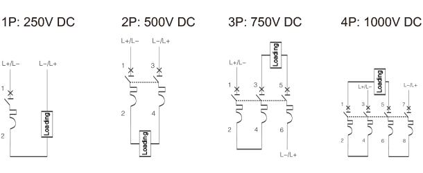
Dc schematics often referred to as elementary wiring diagrams are the particular schematics that depict the dc system and usually show the protection and control functions of the equipment in the substation. Dcc wiring is simpler but intolerant of sloppy workmanship and make do practices. Higher currents heavier power wiring and overload protection must work. Ac systems can have more than one source shore power generator inverter.
Gallery of Dc Wiring Diagram