An octave coupler realised using diode keying techniques. This process is outlined below.

Wiring Diagram For Diode Stack
Diode wiring diagram. Before diving into further detail it is obvious at first glance that diodes are by far the most numerous components in this circuit which explains why the technique is called diode keying. Locate the dinghys factory running light brake and turn signal circuits and install a diode in line with each. The wiring diagram for an octave coupler is shown in figure 7. Diodes are ideal for isolating an alarm keyless entry or remote start from the factory wiring in vehicle. The diode connections reveal how current travels in a single direction in the diode circuit. The diagram below shows how to diode isolate the negative hood and trunk triggers to a single trigger which can be used as the negative instant trigger to an alarm.
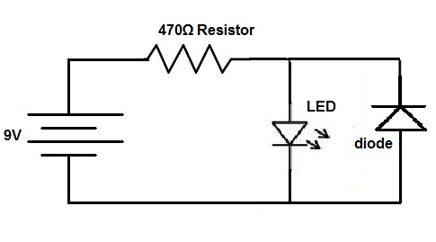
Diodes have a wide variety of applications from transformers to oscillators across areas of physics and electrical engineering. Can i stop this by wiring a diode into the positive plug connection and if so what type and rating of diode would i require. Follow instructions in diode installation to complete wiring. The diodes are needed to prevent a back feed between the hood pin and the factory trunk light circuit. Wiring a plug to the timer would achieve this but would result in the plug positive pin being live when the light is switched on in the usual way. Connect diodes such that electrons flow from the anode to cathode.
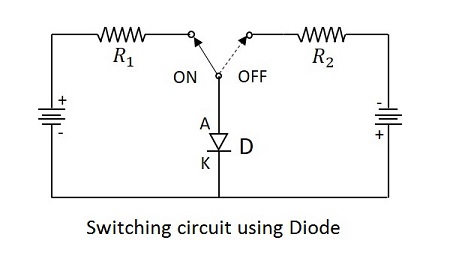
The cathode is the striped side of the diode. The diode installation is the same for each circuit. Diodes are small cylindrical shaped components which are consisted of two leads the anode and the cathode.
Gallery of Diode Wiring Diagram