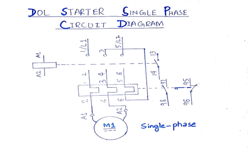
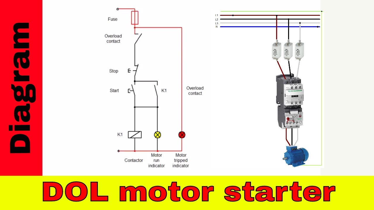
The dol starter connects the 3 phase voltage supply ie. When the start button is pressed current will flow through one phase to the control circuit and the contactor coil to the other phase.

Electrical And Electronics Engineering Direct Online Starter
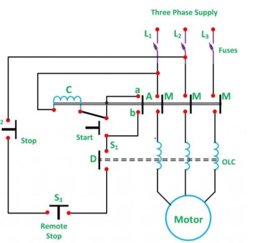
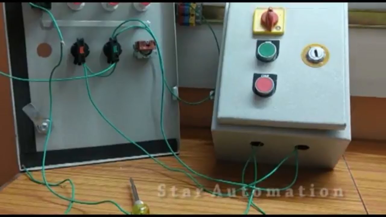
Dol starter remote control wiring diagram. The control circuit and the power circuit. These two buttons ie. Dol starter control power wiring diagram overload indicator wiring in malayalam. The l1 contactor is connected from normally open no to r phase using mccb. Cheap dol starter dcsremotelocal startstop where we should usethe name dol is called as direct online starter. There are two types of circuits in the dol starter diagram given above.
Direct on line starter wiring diagram. The connection of contactor can be done among relay coil supply voltage as well as thermal overload. The main heart of dol starter is relay coil. How dol starter control diagram works when we press the start button to start the motor the relay gets the phase and circuit completed thus coil energizes and contactors produce magnetic fieldthe main contactor closes and motor gets the supply and the motor startswhen we press the stop button the circuit will interrupt and the motor stop. The dol starter comprises of an mccb or circuit breaker contactor and an overload relay for protection. A direct online starter consits of two buttons a green button for starting and a red for stopping purpose of the motor.
I have used the same setup upto 125 kw. Less than 10 hp motor we can use dol starter. Dol starter control diagram three phase. R phase y phase and b phase to the induction motor terminals. And from the motor protection relay nc auxiliary the neutral wire goes to the contactor coil a1 terminal. The wiring of direct on line control circuit starter is following.
In which the neutral n wire goes to thermal overload relay nc contacts the neutral wire is also connected to the light indicator. Normally it gets one phase constant from incoming supply voltage a1when coil gets second phase relay coil energizes and magnet of contactor produce electromagnetic field and due to this plunger of contactor will move and. Working principle of dol starter. Some of the pump application like emergency backup pumps firefighting pumps etc. The complete wiring shown in dol diagram. Green and red or start and stop buttons control the contacts.
The dol starter main terminals are connected between the mains supply terminals and motor terminals while the control circuit is energized with two terminals of three phase supply as illustrated in figure. The wiring diagram for a dol stater is shown below. Akrtechnical dolstartercontrolwiring hi i am abhilash k r welcome to our malayalam youtube channel akrtechnical.
Gallery of Dol Starter Remote Control Wiring Diagram