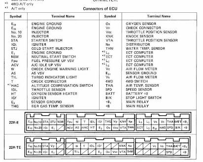
5 d e 19 ac engine coolant temperature switch. Learn how the ect connects and reports its value.

40a3 Ecu Wiring Diagram In Pdf Wiring Resources
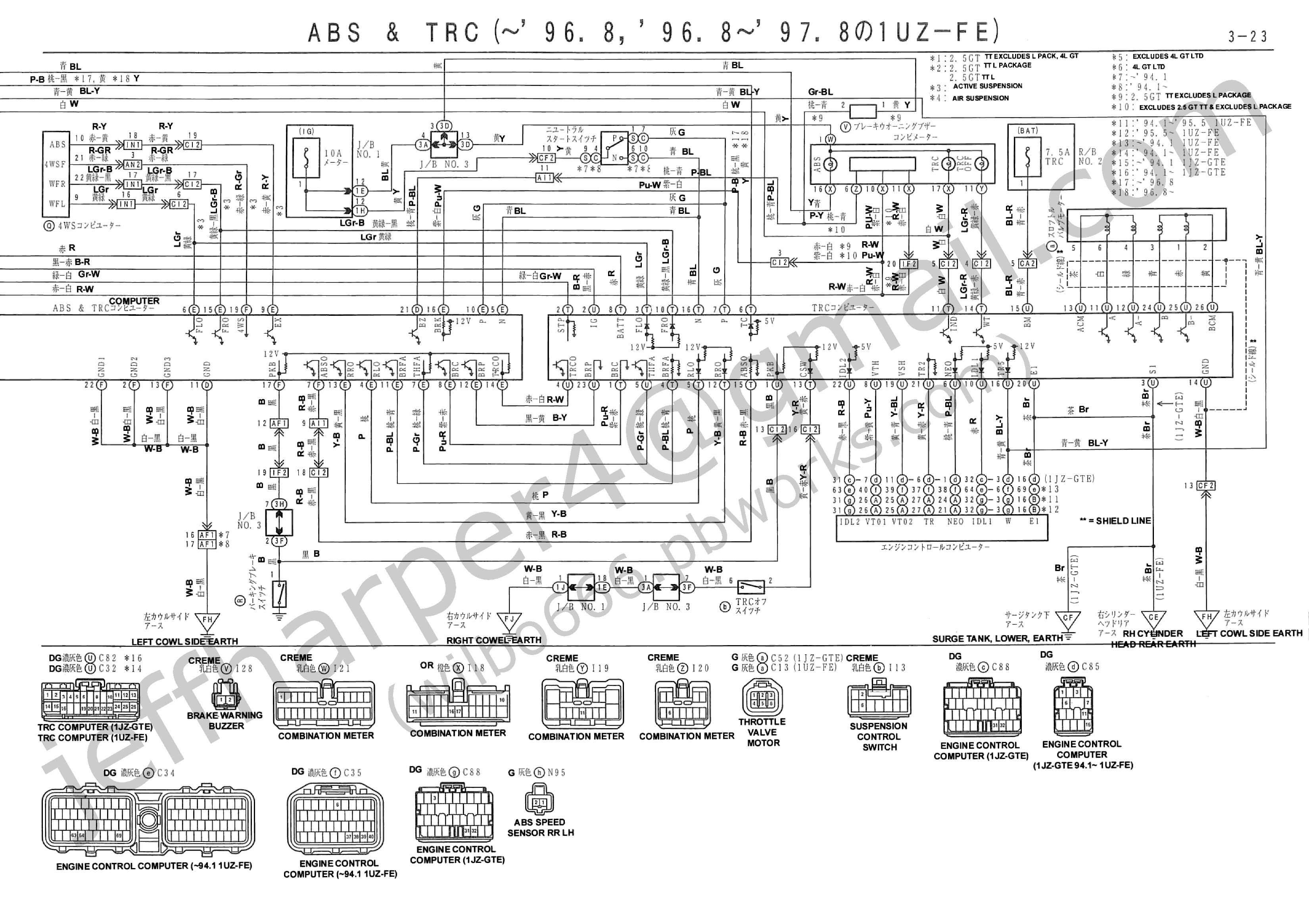
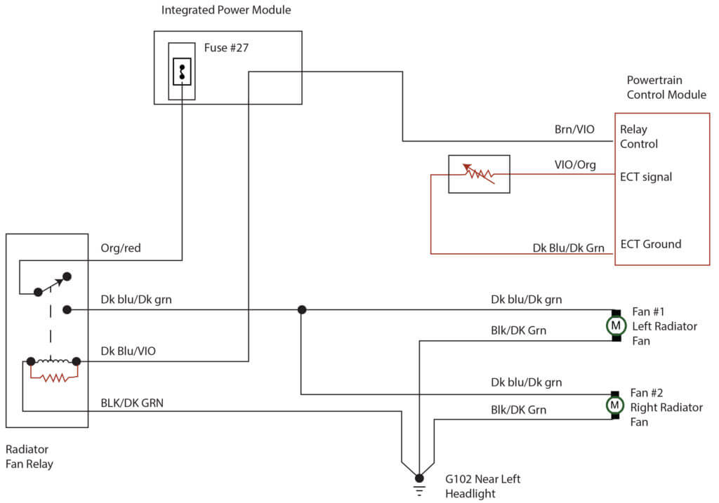
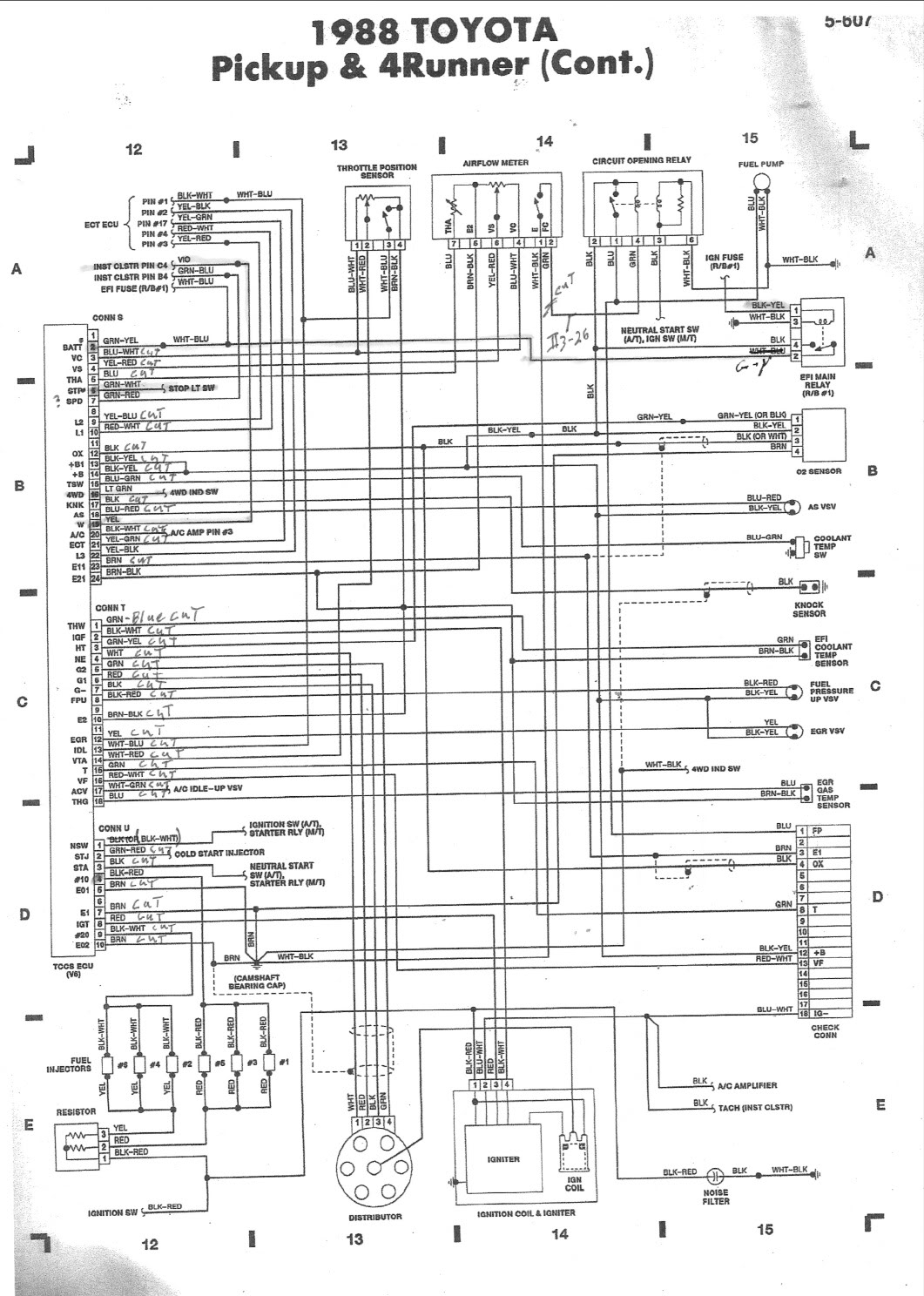
Ect wiring diagram. Power distribution frc 12 wiring diagram. Describe the meaning of the 2 in diagram component s. I just consulted my ford factory 1988 23t wiring diagram and found the 2 circuits for the ect. Describe the meaning of the sd in diagram component t. Wiring diagrams 1993 mitsubishi montero 1993 wiring diagrams mitsubishi wiring diagrams mitsubishi. The ect is a main input to the ecm or engine computer.
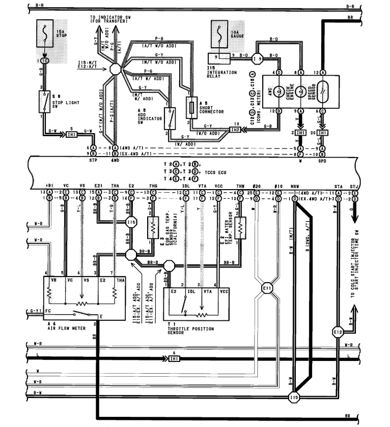
This code indicates that the pcm is seeing a high voltage drop across the ect sensor which its translating as an extremely hot coolant condition. Describe and identify the diagram component u. The engine coolant temperature ect sensor responds to change in engine coolant temperatureby measuring engine coolant temperature the ecm engine control module knows the average temperature of the engine and tells the computer what the engine temperature is so that optimum driveability is realized while the engine is warming up and when the engine has reached operating temperature. A b f71 15a center pin hot a b f60 30a hvac fan a b f61 5a lvd sens vendor ttu a b f76 30a 3968162 a f05 30a lecm4 b f06 20a rh sleeper pwr ports console b. Montero identification component location menu component locations table component figure no. It runs from pin 7 of the ecu to the ect connector.
Engine coolant temperature ect circuit high input. Describe the meaning of the g w in diagram component r. Wiring diagram index name description page aa power distribution frc 3 ab power distribution frc 4 ac power supply circuit protection 34 ef 5 ad power supply circuit protection 44 ef 6 ae grounding 7. It shows the components of the circuit as simplified shapes and the gift and signal friends between the devices. This video explain its electrical connections to the ecm or from an electrical perspective. The ect feed wire is ltgrnyel circuit 354.
Describe the meaning of the c13 in the diagram component q. If your vehicle is not equipped with a working trailer wiring harness there are a number of different solutions to provide the perfect fit for your specific vehicle. The second wire is blkwht circuit 359g. Its the sensor signal return wire and ties in with many other sensors. Location ac compressor relay. Aa spf44a spx03ea3 fb2a1 08 ag0 b a17b2 ai4 c frcj3c5 aq1 b mcsca9 f61a1 08 hb2 d a131ba4 f15a1 50 bi3 c x210aad f87 15a cust.
Coolant temperature sensor wiring diagram repair guides electronic engine controls engine coolant coolant temperature sensor wiring diagram wiring diagram is a simplified enjoyable pictorial representation of an electrical circuit. Understanding toyota wiring diagrams worksheet 1 1. When the pcm senses this high voltage input it will translate this voltage input to a coolant temperature of 46 f 50 c. Complete with a color coded trailer wiring diagram for each plug type this guide walks through various trailer wiring installation solution including custom wiring splice in wiring and replacement wiring.
Gallery of Ect Wiring Diagram