Greddy greddy emanage blue wiring diagram greddy emanage blue wiring diagram schematron g reddy emanage blue wiring diagram wiring diagram database greddy e manage ultimate installation manual download installation greddy greddy e manage jdm manuals. This is a sure way to do that.

Greddy Emanage Blue Ignition Wiring Harness Diy Universal
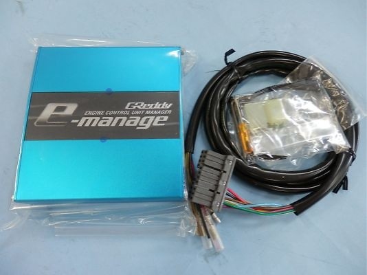
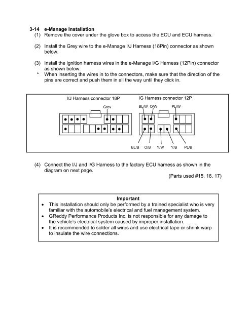
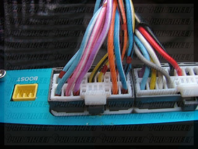
Emanage blue wiring diagram. Emanage blue pin out diagram. Adptraining recommended for you. The e manage system is a universal piggy back type unit which taps into most japanese factory ecu wiring by utilizing the existing sensors. Emanage operation wire signal emanage connector emanage wire color ecu pinout ecu wire color connection type power red 102 or 107 red t solder ground black 101 or 106 black t solder rpm brown 21 black t solder throttle grey 19 greenwhite t solder airflow input light blue 10 from mas greenblue connector. E manage blue installation verification before strapping your rig to a dyno or hitting the track every effort should be taken to insure the e manage is working correctly. Basic functions will allow the user to slightly alter factory injector duty cycle 20 at 5 preset rpm points by intercepting and altering airflow or map sensor signals.
Emanage blue pin out diagram. Injector circuit wiring diagram duration. A laptop win98se pii with 196mg or better greddy support tool and a cable. Skip navigation sign in.
Gallery of Emanage Blue Wiring Diagram