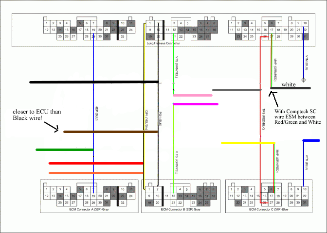
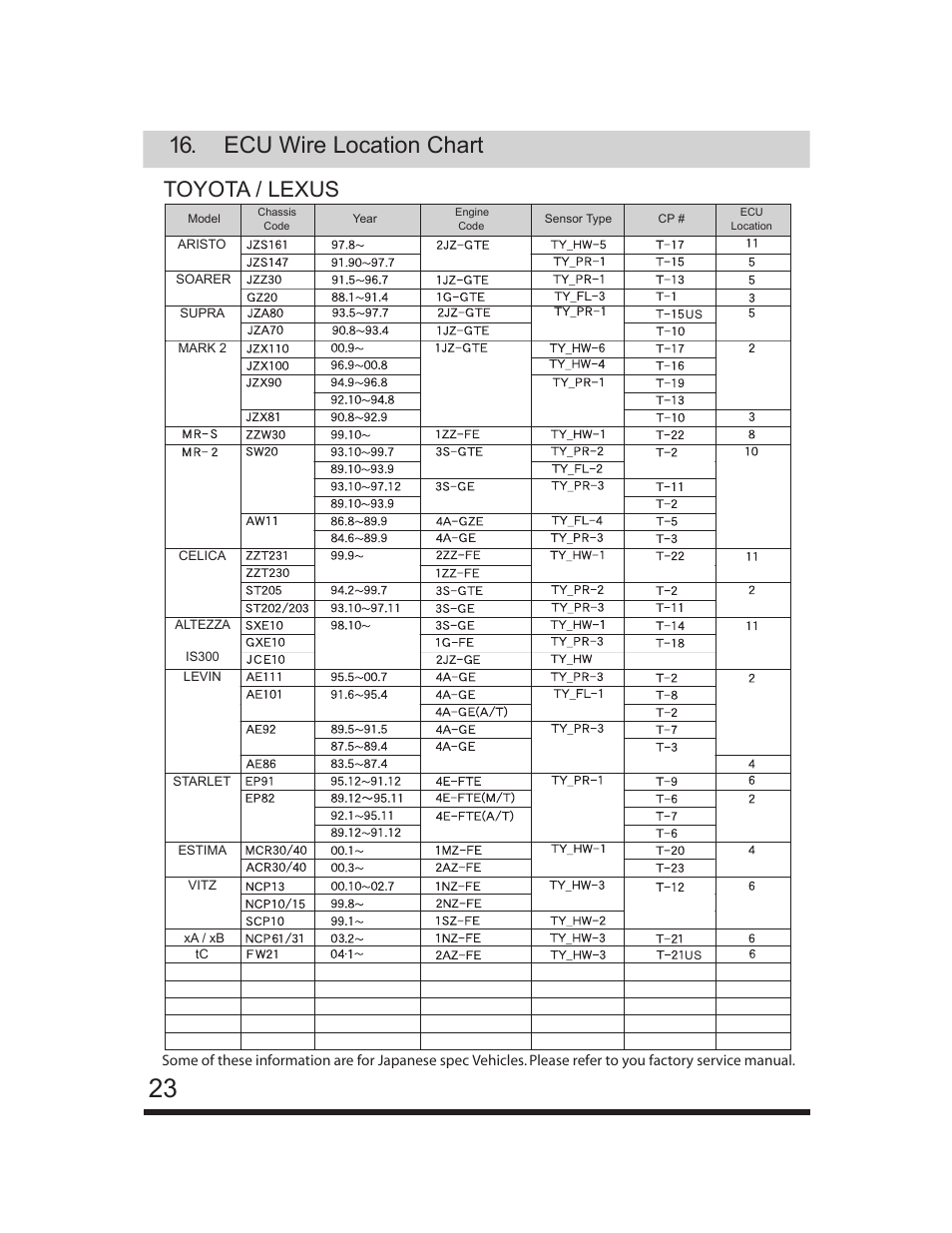
Wiring whatever you do dont look at the ecu wire location chart at the back of the emanage manual. At the top of the instructions it says all internal emanage.
No Spark After Installin Greddy Emanage Mitsubishi 3000gt
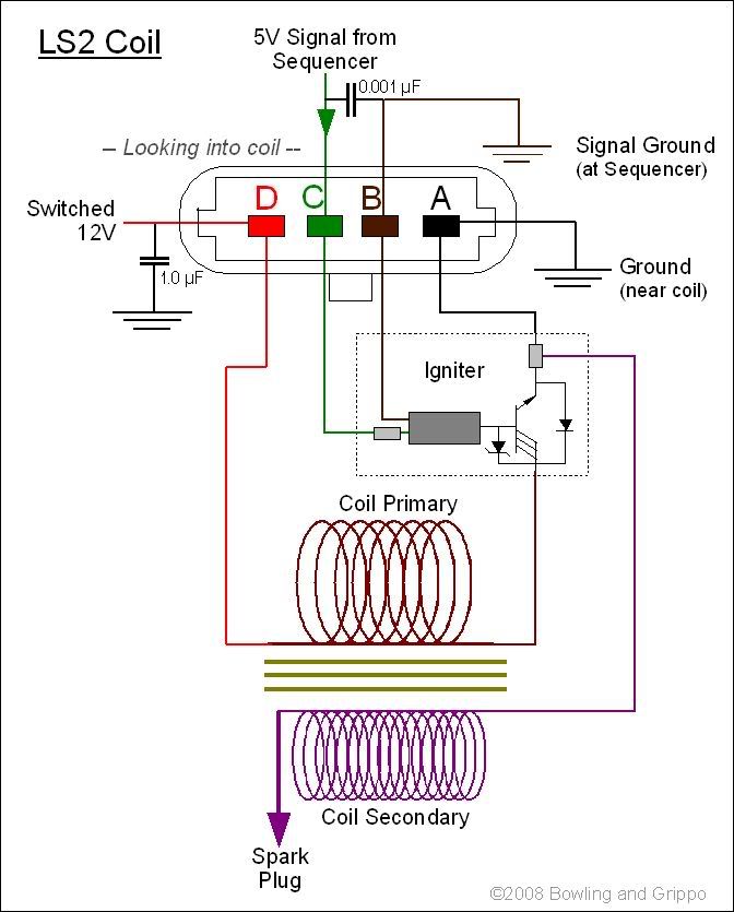
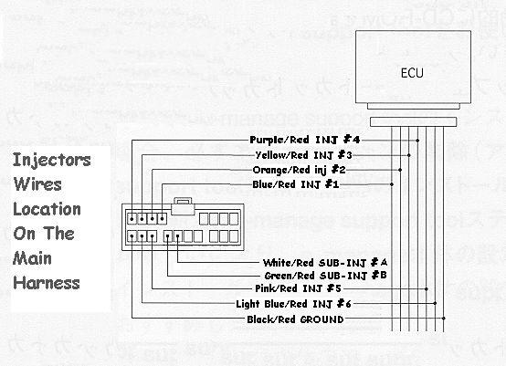
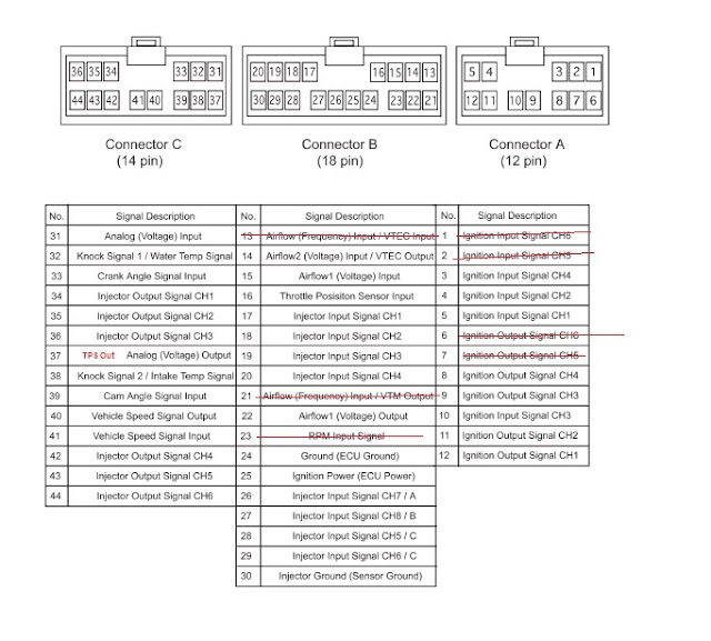
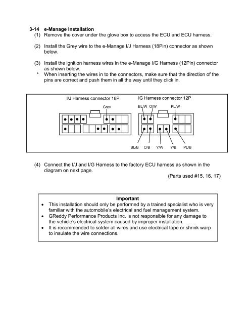
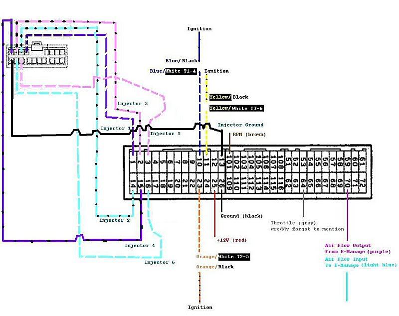
Emanage wiring diagram. Ignition signal wire connect the e manage ignition channels in the engines firing order shown in the chart below. Injector w iring the e manage ultimate has upgraded the injector adjustment feature. Any help would be appreciated. Improper tuning of the e manage ultimate can cause damage to the engine. Greddy emanage blue wiring diagram. When making wire connections be sure to remove the key from the ignition and disconnect the negative terminal of the battery.
Never short out the system. Installation and tuning information. The e manage ultimate has added connector c for more functions. Greedy emanage wiring instructions these instructions are for the 1zzfe spydercelica. The initial installation consists of the same basic connections as an apex afc. The emanage has a lot of functionality considering it is still a piggyback type engine.
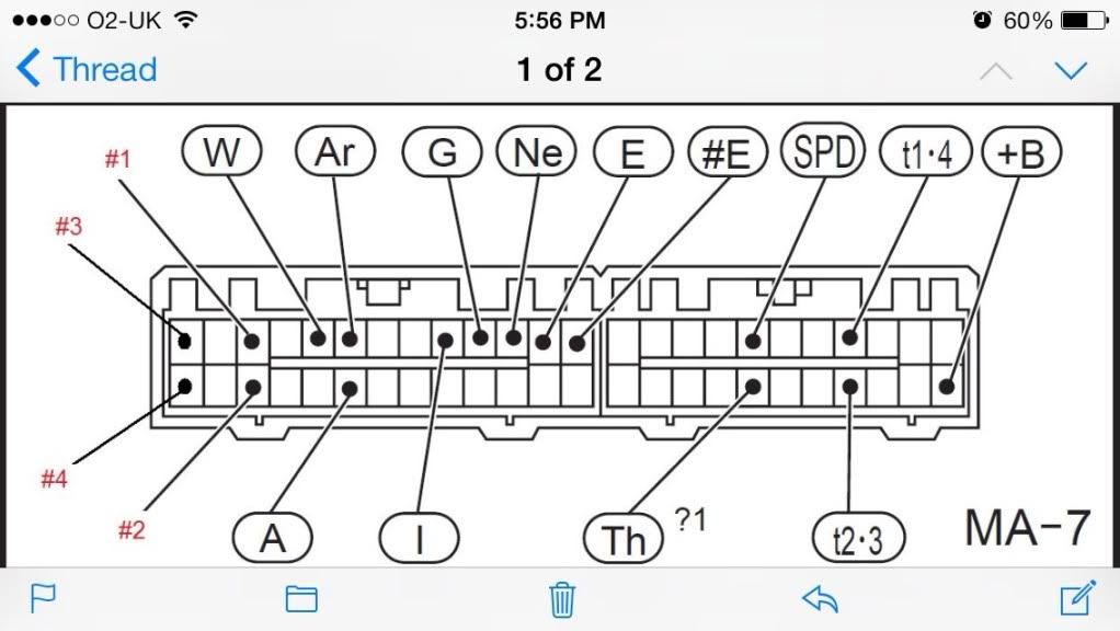
It can damage the unit as well as the vehicles electrical system. Skip navigation sign in. Emanage blue pin out diagram. Can anyone get me a pic of their diagram or give any advise on what to do. Injector circuit wiring diagram duration. Emanage blue pin out diagram.
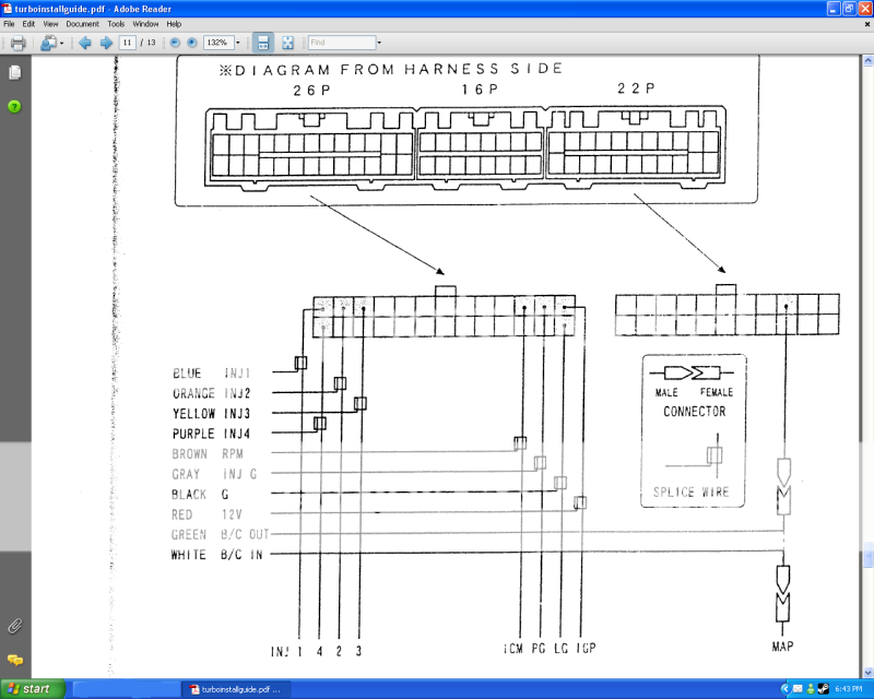
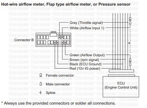
E manage ultimate pin diagram connectors a and b are the same as the e manage. Greddy read and fully understand the wiring diagram before making any. It is completely wrong and is only there to confuse you. Adptraining recommended for you. Firing order chart e manage channels 3 4 6 8 cylinder distributor 3 cylinder individual ignition 4 cylinder inline group ignition t14 t23 4 cylinder horizontally opposed group ignition t12. The guy i bought it from got it for a different car so it wont come with a wiring diagram but it does have a universal wiring harness.
I just bought an e manage ultimate and i am planning on putting it on my 04 celica gt s. These are power ground rpm signal throttle position signal airflow input and airflow output. Read and fully understand the wiring diagram before making any wire connection.
Gallery of Emanage Wiring Diagram