Specifications electrical inputoutput voltage 24vdc 48vdc240vacexternalcircuit current 1aat24vdc 1aat48vdcexternalcircuit frequency 5060hz circuitsqty 9. In this episode we will learn how emergency push buttons are wired the correct way.

Start Stop Button Wiring Diagram Auto Electrical Wiring Diagram
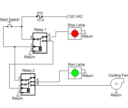
Epo button wiring diagram. 20 1 1995 and 1999 teal electronics corporation the emergency power off epo button is a common feature in many medical industrial and data processing facilities. The diagram in cascade multiple epo. The diagram in cascade multiple epo. The controls on all of these units are powered by a 24 volt transformer. If the boiler room door is on the exterior the switch should be located just inside the door. Emergency power off circuits application note an 16 app note an 16 rev.
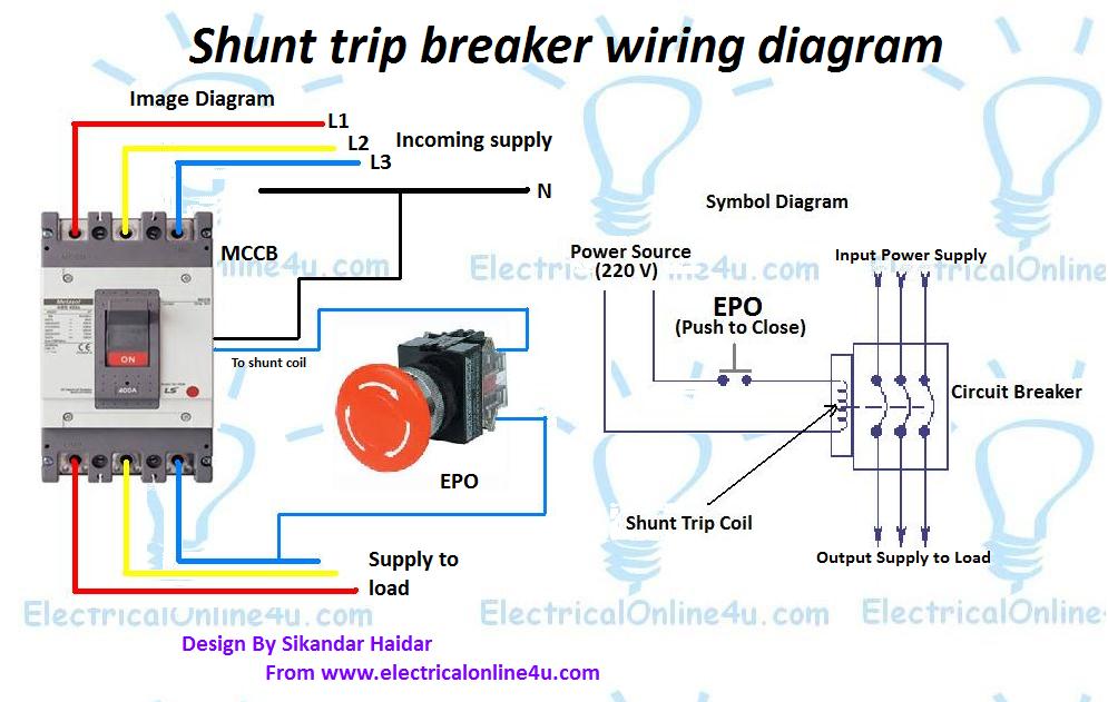
In this post i am just tell you about wiring of single epo button with shunt trip mccb breaker. Epo circuits provide a fast simple method of shutting down power to a room or piece of equipment. It shows the parts of the circuit as streamlined shapes and also the power and signal links between the devices. Switches with lockout latch when you depress the button and can be locked in that position using a padlock with a max. And why not the other way. If wiring the switch and the bulb to the same circuit the circuit voltage must not exceed bulb voltage.
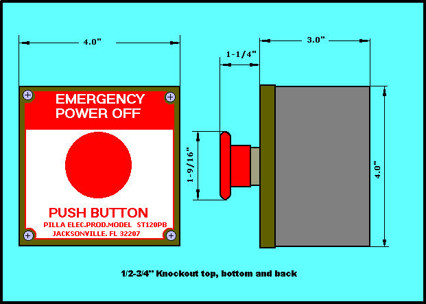
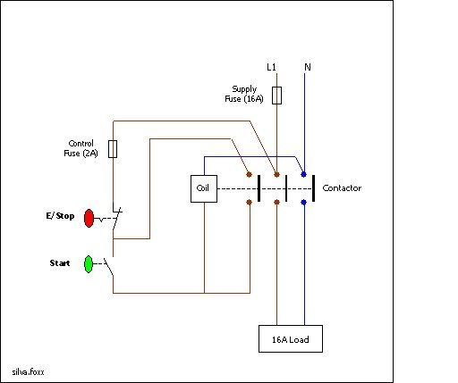
Consideration should be given to type and location of the switch to safeguard against tampering. Replace contact blocks sold separately or add additional contact blocks to control more circuits. The solder on the wire provided mechanical strength and keeps the wires together when the screw is tightened down. You can route the red wire attached to the 24 volt side of the transformer through your normally closed epo contacts. Consider support via donation from the link upper right. A manually operated remote shutdown switch or circuit breaker shall be located just outside the boiler room door and marked for easy identification.
With just two wire terminals on the 24 volt side. They are held down by the retaining screws on the switch assembly. Plus when you bend the wire into a curved shape it retains it better. Shunt trip breaker wiring diagram with epo button. There should be a wiring diagram glued to the inside of the units electrical control panel however. It provides detailed electrical and physical specifications diagrams.
A wiring diagram is a simplified conventional photographic representation of an electric circuit. The wired that go on the switch are soldered but not soldered onto the switch. In industrial state electric operator duty is to operate the machinery and his duty is on the front of main panel board. Collection of apc epo wiring diagram. Only certified electricians may install the system and the wiring to the products it the emergency power off epo system consists of one or more wall mounted push button epo boxes.
Gallery of Epo Button Wiring Diagram