Wellborn variety of gfci wiring diagram feed through method. March 5 2019 by larry a.

3 Way Switch Variations
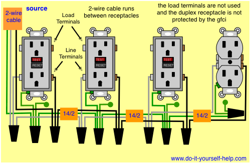
Gfci wiring diagram feed through method. A wiring diagram is a streamlined traditional pictorial depiction of an electric circuit. Gfci outlet wiring method this article and the electrical wiring diagram will show you how to install a gfi using the feed through method which will protect more than one outlet. This article and the electrical wiring diagram will show you how to install a gfi using the feed through method which will protect more than one outlet. Gfci receptacle in a series with an unprotected outlet. Gfi wiring diagram using the feed through method a typical application for this method would be to protect more than one bathroom or the all of the receptacles in your garage. Gfci wiring method with an unprotected light.
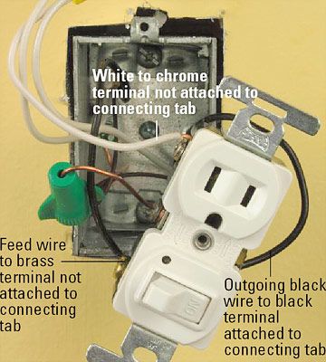
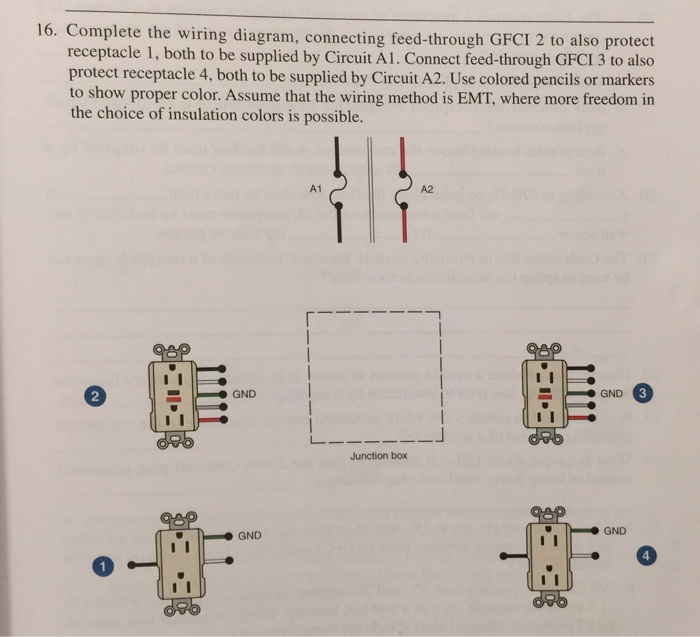
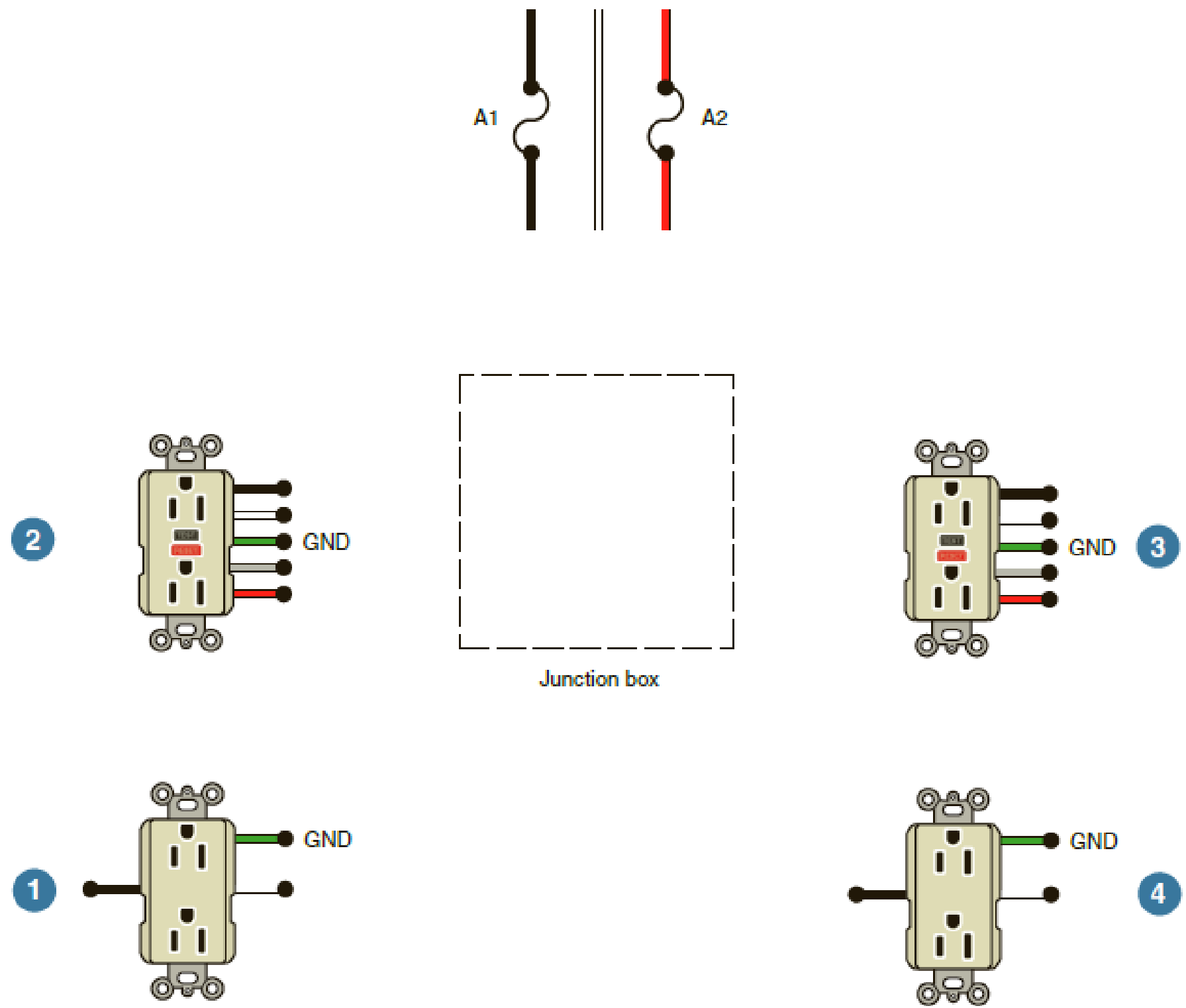
Use colored pencils or markers to show proper color. Extensions to knob and tube electrical wiring fluorescent lights superb light circuit diagram 15 unbelievable wiring diagram 3 way light switch collection gfci feed through method how to wire a garage diagram with awesome fluorescent fine light. These instructions will probably be easy to comprehend and implement. If there is only 1 cable containing 2 3 wires connect the white line wire to the silver or white terminal and connect the black wire to the brass terminal which is the. 2wire gfci wiring diagram wiring diagrams thumbs gfci wiring diagram. Its supposed to assist each of the average consumer in developing a suitable method.
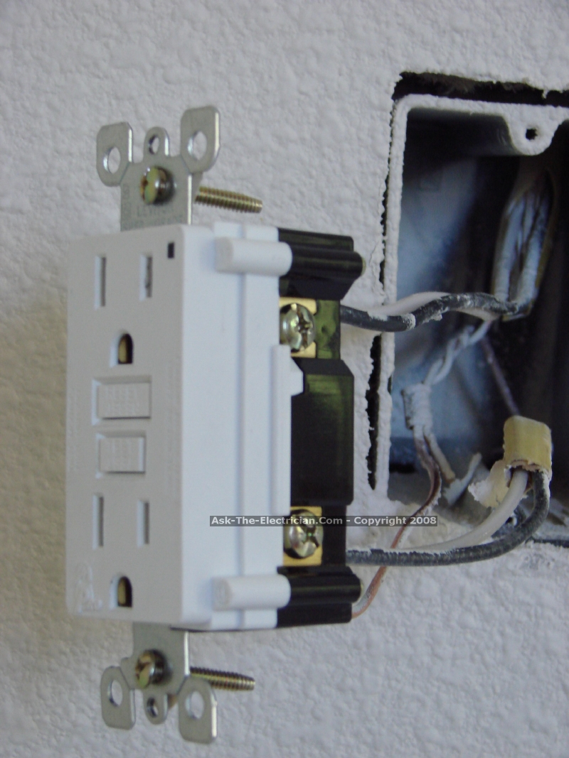
Visit the post for more. It works by comparing the input current on the ungrounded side red wire to the output current on the neutral side black wire. Wiring a gfci receptacle is a little more complicated than hooking up a regular outlet but easily learned once explained. If you are replacing an existing gfci outlet with a new one we suggest that you read our page about replacing a gfci outlet. This diagram illustrates the wiring for a circuit with 2 gfci receptacles followed by an unprotected light and switch. How to wire gfci outlets.
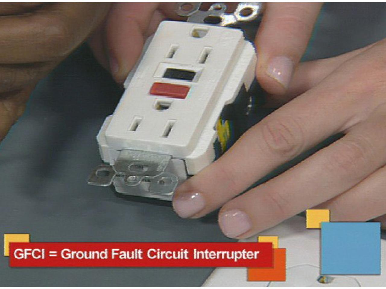
You can also learn about wiring gfci outlets in the following 7 steps. Ground fault circuit interrupter gfci is a device which secure person from electric shocks from faulty currents in the electrical devices we use in our daily lives. Connect feed through gfci 3 to also protect receptacle 4 both to be supplied by circuit a2. Single gfci wiring diagram gallery. Using this wiring method the light circuit is not protected from ground faults. The light switch terminal is connected directly to the source coming from the circuit.
It reveals the parts of the circuit as simplified shapes and also the power as well as signal connections between the tools. Wiring diagram comes with several easy to stick to wiring diagram instructions. Assume that the wiring method is emt where more freedom in the choice of insulation colors is possible. To properly wire gfci or ground fault circuit interrupter receptacles turn off the power to the circuit youre working on and unscrew the cover plate on the outlet box. Gfci outlet wiring diagram.
Gallery of Gfci Wiring Diagram Feed Through Method