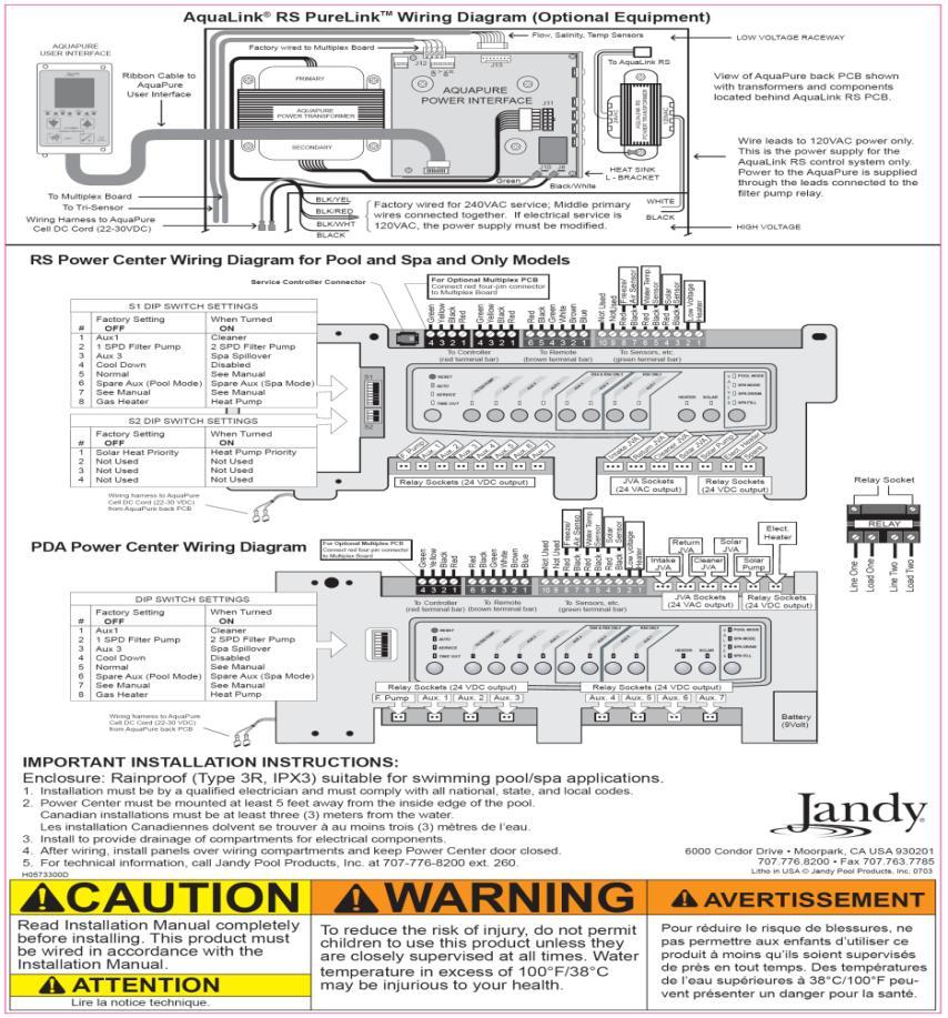
Connect the orange plug running from the jva relay. In canada all wiring must be done in accordance with the canadian electrical code csa c221.
8252 Pda Wireless Remote Controller J Box User Manual
Jandy valve actuator wiring diagram. The toggle switch reverses the setup if the valve moves one way when. For address information see back cover. Using this relay board. The cams on the motor shaft and micro switches are used to stop the motor at the desired position. Jandy valve actuator wiring diagram 10 illustrated layouts of swimming pool equipment plumbing using jandy valves. Board use the pc.
Build the perfect pool environment with jandy professional grade swimming pool equipment. Procedures in this manual must be followed exactly. To obtain additional copies of this manual contact 707 776 8200 ext. Page 14 low voltage wiring minimum wire size should be 22 awg. With a full line of pumps filters heaters lights valves water sanitizers and the automation solutions to control it all jandy has the complete equipment package for any swimming pool or spa. Build the perfect swimming pool environment with jandy professional grade swimming pool equipment.
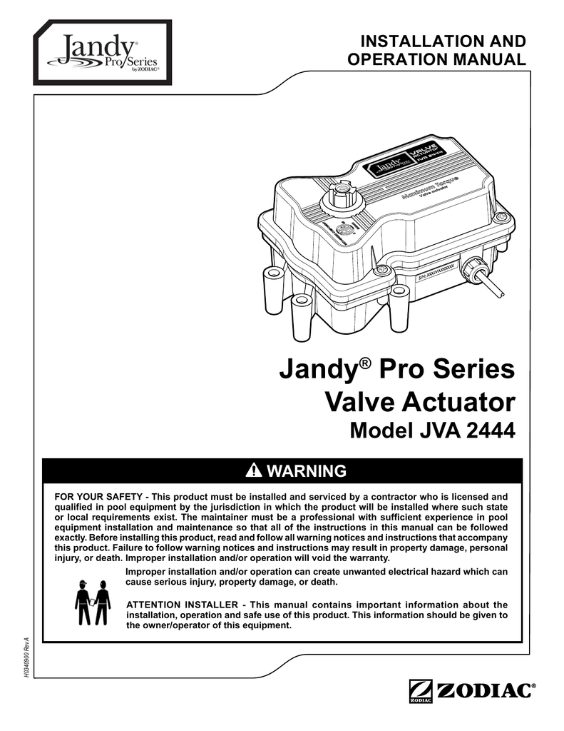
Installation and operation of jandy valve actuators jva. All wiring must be done in accordance with the national electrical code nec nfpa 70. A jandy valve actuator jva relay board allows you to activate a jva from an auxiliary button. It is available in 15 x 2 2 x 25 and 25 x 3 sizes. The cam positions are adjustable. Plug it into the 24v power socket on the jva relay board.
Equipment installation and maintenance so that all of the instructions in this manual can jandy pro series valve actuator installation and operation. Here is an electrical schematic of the inside of a jandy valve actuator the pentair is likely similar. With a full line of pool products including pumps filters heaters lights valves water sanitizers and the automation solutions to control it all jandy has the complete pool equipment package for any pool or spa. 22 description jandy valve actuators are designed to meet the needs of todays more advanced automatic pool equipment. Volt jandy pool and spa light wiring diagram vac power supply jandy light junction black black v12v gfci neutral transformer white white page low voltage wiring. The jandy pro series valve actuator fits all jandy pro series neverlube and gray 2 and 3 port diverter valves in 24v models and works seamlessly with the aqualink rs control system.
I have aqualink rs8 main pump booster pump heater blower and 2 actuators controlling pool spa and water feature. Board wiring diagram to locate this plug. Adjustable 24 volt actuator for versatile pool and spa automation. The jandy valve actuator which connects to a jandy pool controller system. Page 4 english jandy pro series valve actuator installation and operation manual. All applicable local installation codes and regulations must be followed.
Gallery of Jandy Valve Actuator Wiring Diagram