Honda c65 cub electrical harness wiring diagram schematic 1964 1970 here. Follow diagram with separate transformer if furnace transformer not sized to handle additional load.

Read Or Download 36 Volt Battery Wiring Diagram Trolling
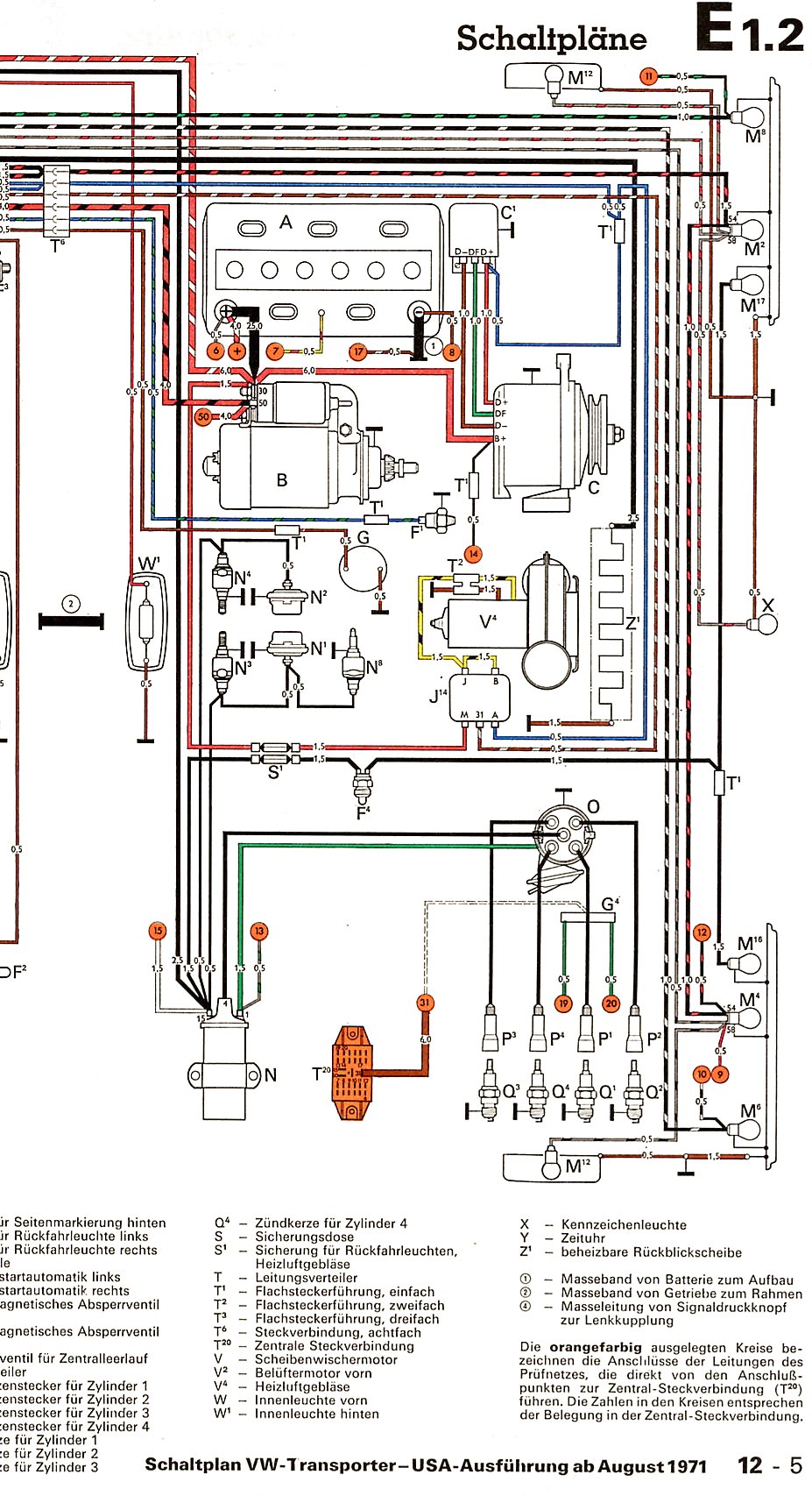
Hn65ct003b wiring diagram. Lockoutreset relay wiring diagram. The associated wires as also included. Factory authorized parts hn65ct003 relay factory authorized parts are designed to meet exact carrier corporation specifications ensuring optimum system performance proven reliability easy installation and maintenance and safe system operatio. Honda motorcycle electrical wiring diagram schematics. Thanks for looking and good luck. Honda c70 cub electrical harness wiring diagram schematic.
Eard dampers use approx. View profile view forum posts visit homepage view forum threads professional member join date jul 2004 location london on posts 500 post likes mentioned 0 posts tagged 0 threads. Honda c50m c 50 electrical wiring harness diagram schematic here. Factory authorized parts 38hq660014 compressor lockout sensing relay. Ccaarrrriieerr sseennssoorrss iinnssttaallllaattiioonn gguuiiddee carrier corporation 2020 catalog no. Nom kw at 240 v label diagram kfceh0101h10 10 smart heat fig.
This is a brand new oem carrierbryantpayne control circuit board kit. The carrierbryantpayne part is 38hq660014 and it contains a board with part hn65ct003b also lr50808 296 101 296 83 105b. 1 see diagrams on pages 1 4 for heatcool system wiring. 18 kfceh0201h15 15 smart heat fig. Honda c50 super cub electrical wiring harness diagram schematic here. 22 wiring diagrams fan coils accessory electric heaters.
The associated wires as also included. Number 006 008 208230 3 60 460 3 60 11720011 c 1 575 3 60 012 208230 3 60 014 460 3 60 11720960 b 2. 19 kfceh0301h20 20 smart heat fig. The carrierbryantpayne part is 38hq660014 and it contains a board with part hn65ct003b also lr50808 296 101 296 83 105b. Honda anf125 wave 125 electrical wiring harness diagram schematic here. 20 fan coil with cooling only control label diagram pf1mn018024030036042048060070000aaaa fig.
02 05 2006 1021 am 1. Wiring diagrams index unit 50byn v ph hz label diagram fig. 2 u switch down c r 1 2 furnace or air handler vent vent m36914 s s y y2 g c u u a w2 w k rc r la e aux eard damper ob eard fresh air damper powered by a.
Gallery of Hn65ct003b Wiring Diagram