Select desired time delay adjustable models only. 18 240 vac frequency.

Dayton Timer Relay Wiring Diagram
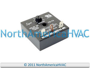
Icm203 wiring diagram. A wiring diagram is a simplified traditional pictorial depiction of an electric circuit. Icm controls icm203 icm203 delay on break timer 03 10 minute knob adjust. 1 amp minimum. Connect terminals as shown in the wiring. For 24 vac circuits apply control as packaged. The compressor will not start again during the delay period.
A wiring diagram is a simplified traditional pictorial representation of an electrical circuit. Ac air conditioning refrigeration and heat pump delay on break timer part icm203. Mode of operation with application of power the load is energized. When the initiate contact closes the load energizes and remains energized as long as the initiate contact is closed. 50 60 hz output output ratings. Delay on break timer with 03 10 minute adjustable time delay universal 18 240 vac.
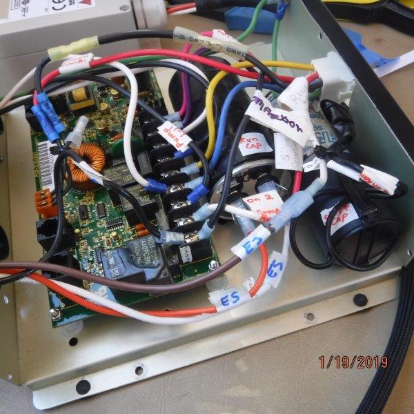
Delay delay on break timers anti short cycle on delay on break helps to protect air conditioning refrigeration and heat pump equipment from damage which may be caused by the rapid short cycling of compressors. 40 ma inrush. Delay on break delay on de energization. When the thermostat opens or there is a loss of power the load is de energized and the delay period begins. Wiring diagram y r c tstat contactor compressor control transformer line voltage 1. Delay on break timer wiring diagram.
Connect terminals in series with the starting device as shown in the wiring diagram below. Wiring diagram replaces thermal time delays off delay purges ducts of residual air to increase efficiency power must be applied before and during the time delay period. Control circuit wiresmode of operation. Timing diagram icm controls. Connect terminals as shown in the wiring diagram below. Icm controls icm203 icm203 delay on break timer 03 10 minute knob adjust.
Collection of icm254 wiring diagram. It is perfect to use when either a magnetic lock or electric strike is installed on an automatic door. 10 amps time delay 10 1000 seconds timing diagram 1. For 120240 vac circuits cut the jumper wire. It shows the components of the circuit as simplified shapes and also the power and also signal links between the devices. Select the desired time delay.
Wiring diagram input 18 240 vac 1 2 3 load mode of operation installation specifications input voltage. 14 icms line voltage monitors were specifically. Mode of operation upon application power the load is energized. Buy icm controls icm203 delay on break timer 18 240 vac 125 height 2 width 2 length. Reapply power check operation.
Gallery of Icm203 Wiring Diagram