Iec 60947 3 wiring diagram fresh 3 phase motor starter wiring architectural wiring diagrams act out the approximate locations and interconnections of receptacles lighting and steadfast electrical services in a building. Wiring diagram book a1 15 b1 b2 16 18 b3 a2 b1 b3 15 supply voltage 16 18 l m h 2 levels b2 l1 f u 1 460 v f u 2 l2 l3 gnd h1 h3 h2 h4 f u 3 x1a f u 4 f u 5 x2a r power on optional x1 x2115 v.

Manual Yunnan Lathe Electrical Simplebooklet Com
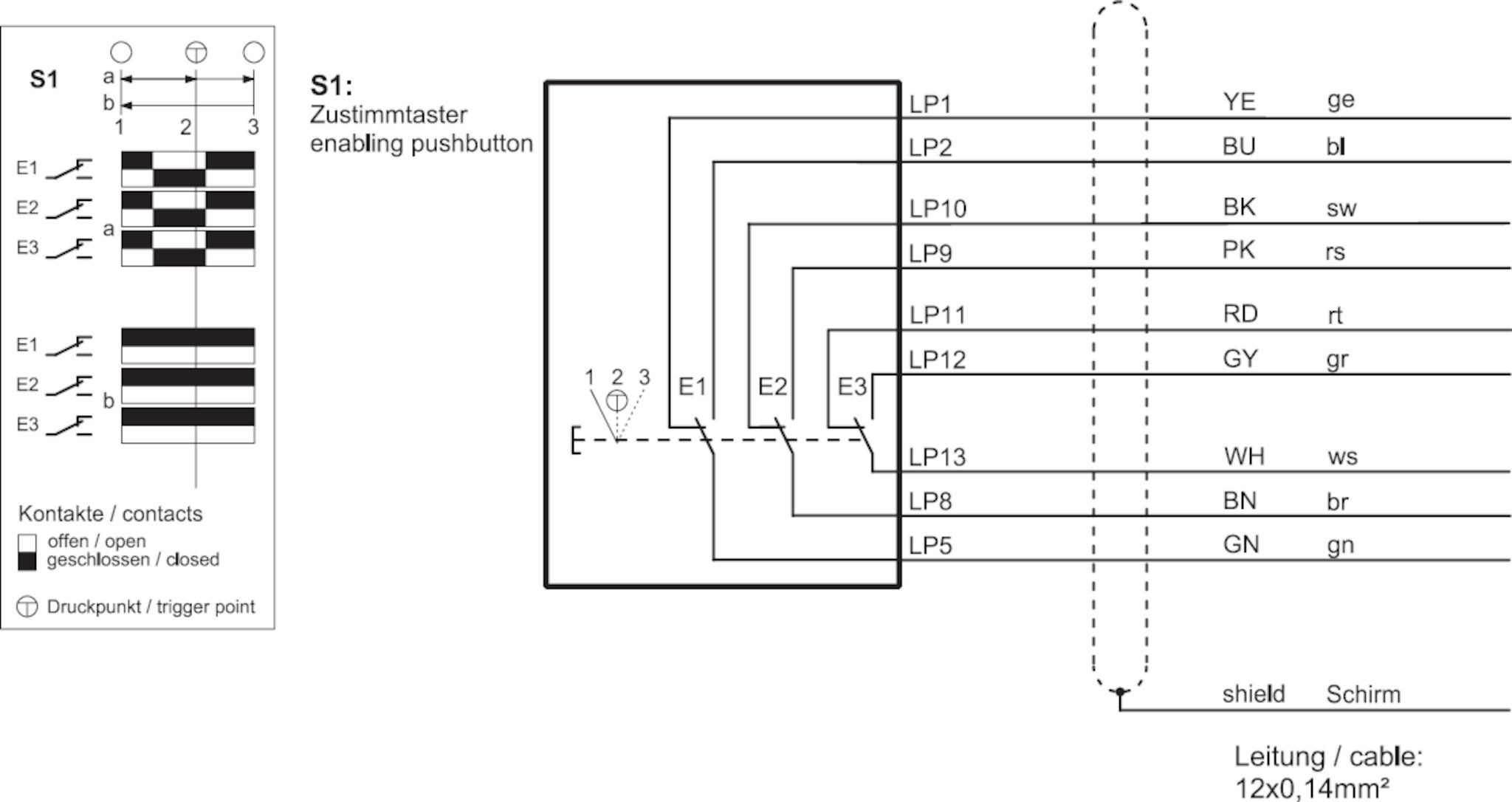
Iec 60947 3 wiring diagram. The authors thank the international electrotechnical commission iec for permission to reproduce information from its international standard. Eaton qsa plug in switch disconnector fuses add on aux. Atys p associated to an inputoutput module can deliver a signal to the motorised switch in order to realise the load shedding. Current limiting circuit breaker iec 60947 2. Contactor utilisation categories iec 60947 4 1. Pin number wire color signal.
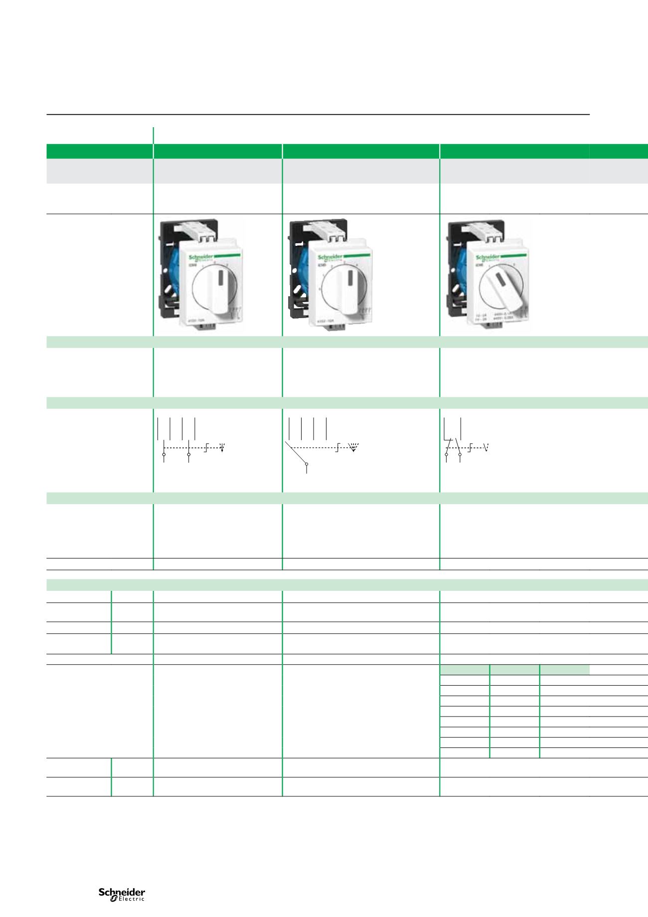
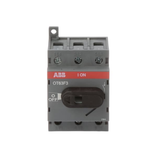
Compliance to iec 60947 3 ideal for motor protection ac23 rating unique moving contact systems. Table 3 nema and iec controller markings and elementary diagrams nema power terminals control terminals coil terminals iec. Circuit breaker utilisation category iec 60947 2. Circuit breaker iec 60947 2. Relay electrical iec 60947 1. Contacts for remote indication plug in for easy replacement on site self extinguishing material 690v ac kema certified compliance to iec 60947 3 ideal for motor isolation.
Iec 60947 5 1 control circuit devices and switching elements. Make contact iec 60947 1. Iec 60947 1 low voltage switchgear and control gear. 4 ple per iso 13849 1 type 4 interlocking device according to iso 14119 with either low standard or high unique. Ups 230vac critical loads non critical loads. Requirements specific to e stops are found a few sections later in the iec 60947 document.
Interconnecting wire routes may be shown approximately where particular receptacles or fixtures must be on a common circuit. Socomec technologies benefits fully compliant with iec 60947 6 1 power supply taken from an existing ups load shedding principle diagram. Refine your search with our advanced search form. Download kedu switch wiring diagram en 60947 1 close download and application of low voltage switching and control devices and does not claim to iec ed iec am2 iec ed. Connect the sensor to 24v dc see typical wiring diagram on page4 table 2 8 pin unit for help. Please read our search engine faq or contact us if you cant find what you are looking for.
Iec 60947 1 ed50 2007 iec 60947 4 1 am2 2005 iec 60947 2 ed40 2006 iec. General rules this is the general standard giving requirements for all low voltage control gear.
Gallery of Iec 60947 3 Wiring Diagram