The angular velocity of a shaft. To be increased electronically to 5000 or 10000 pulses per revolution see diagram below.

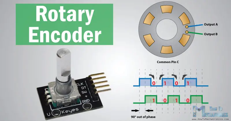
In Depth How Rotary Encoder Works And Interface It With Arduino
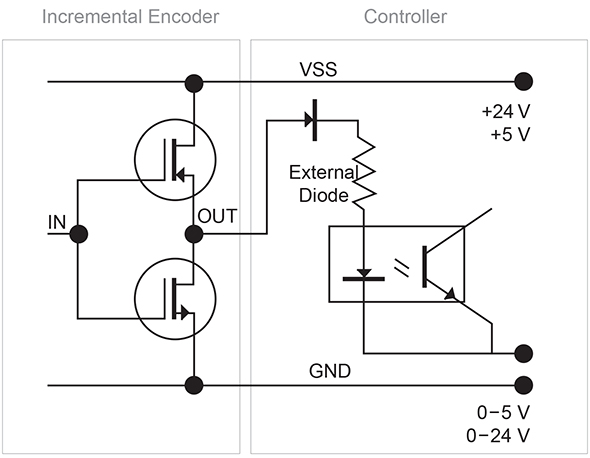
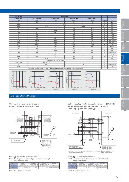
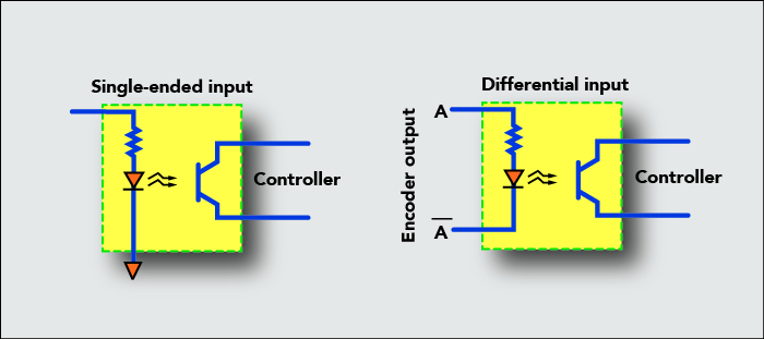
Incremental encoder wiring diagram. Hs35 incremental ordering options for assistance call 800 350 2727 use this diagram working from left to right to construct your model number example. Quadrature encoders have dual channels a and b phased 90 electrical degrees apart. 41 device overview fig. All notes and tables referred to can be found on the back of this page. Such an encoder with differential wiring has six wires total and each channels wire pairs feed twin signals to a controller that discards errors to clean the input. Refer to the wiring diagrams and pinout and phasing tables for specific information on each option.
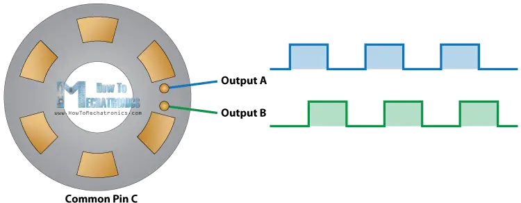
Basically this step is the minimum amount you can rotate the encoder to register any change. The incremental encoders emit electrical pulses that can be used to determine position and cal culate speed. To illustrate other incremental encoders have three channels of data transmissiona b and z for indexing to a setpoint. General information channel a channel b single evaluation double evaluation quadruple evaluation encoder basics. Multi channel differential encoder wiring with commutation tracks can have up to 14 wires and miswiring can result in signal issues such as deformed pulses low signal amplitude and shorted connections. Example encoder with hollow shaftfig.
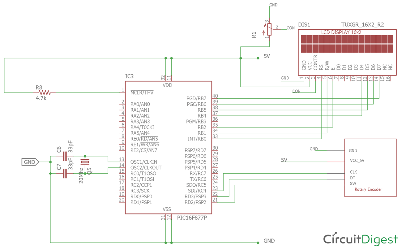
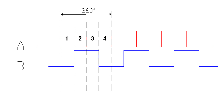
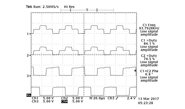
In order to observe rotary encoder pulse output intuitively ato use a plc with high speed counter. Phase a channel typically leads phase b channel for clockwise shaft rotation. Connect the red wire of the servo motor to the external 5v supply the blackbrown wire to ground and the orangeyellow wire to the pwm enabled pin 9. Wiring diagrams are shown for zone 1 and zone 2 applications. Incremental encoders are available in two basic output types single channel and quadrature. Ato encoder is an incremental rotary encoder with 600 ppr npn output solid shaft and ab phase.
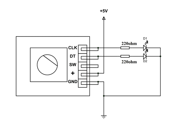
Encoder wiring schemes can be unique to each encoder and one should follow the diagram or pinout designated on the encoder datasheet. On most rotary encoders when you rotate them you will feel a bump known as steps and most rts have about 12 of these per rotation some have 24 or more. A single channel encoder often called a tachometer is normally used in systems that rotate in one direction only and require simple position and velocity information. Each method of wiring has its advantages and drawbacks. As the wiring diagram shows youll need a servo motor. A rotary encoder rt is a device that you can rotate infinitely.
Hs35 express encoders items highlighted with are standard express. Example encoder with solid shaft 42 operating principle encoders detect rotational movements eg. Output signals of incremental encoders this enables the resolution of a two channel encoder with 2500 lines per rev. For bidirectional operation of the encoder proper phasing of the two output channels is important.
Gallery of Incremental Encoder Wiring Diagram