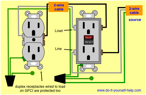
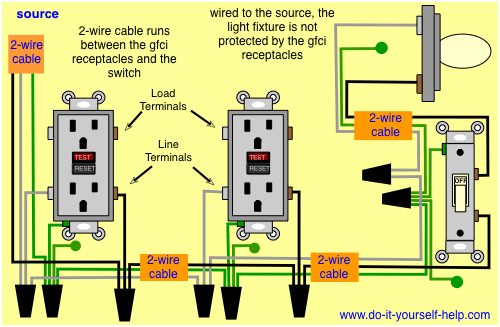
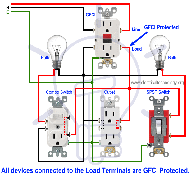
In the first wiring diagram the connected load as light bulb is gfci protected as it is control by the combo switch and connected to the load terminals of gfci. This diagram illustrates wiring a gfci receptacle and light switch in the same outlet box a common arrangement in a bathroom with limited space.

Nb 5963 Gfci Wiring Diagram 110v Wiring Diagram
Kitchen gfci wiring diagram. Kitchen gfci wiring diagram wiring diagram is a simplified customary pictorial representation of an electrical circuit. If more than 1 black and 1 white conductor are in the electrical box also loosen the load side silver and brass terminal screws. This wiring provides single location gfci protection. Today 12 gauge wire is wrapped in a yellow sheath but your old cable may be white. How to wire gfci combo switch and outlet gfci switchoutlet wiring diagrams. In the gfci mainly two wires connect as also shown in a diagram the current flowing from the source and coming back are some due to current laws.
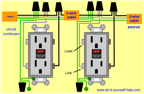
Gfci wiring this list of articles will help you learn about the features and benefits provided by gfi and gfci receptacles and how they are wired. The hot source is spliced to the line terminal on the receptacle and to one terminal on the light switch. Direct main power supply. Wiring a gfci outlet and a light switch. Wiring a gfci outlet with a light switch. In the second wiring diagram the lamp is connected directly to the line terminals of gfci ie.
This often involves adding electrical circuits and adding gfci andor afci protection. It shows the components of the circuit as simplified shapes and the skill and signal associates with the devices. Here the gfci outlet the switch and disposal are all protected from ground faults. Fully explained photos and wiring diagrams for kitchen electrical wiring with code requirements for most new or remodel projects. Refer to the diagram above about wiring gfci receptacles for additional help. So gfci designed as checking the difference between the current leaving and returning through current transformer of the gfci to protect device exceeds 5ma.
Loosen the silver and brass terminal screws on the line side of the outlet. In the first diagram the single way switch and light bulb is connected to the load terminal of gfci. This diagram illustrates the wiring for a cooper gfci combo switch device to control a garbage disposal. If a load plugged into the outlet or the disposal causes a short the whole device will trip and neither will work until the danger is removed. This way the switch and light bulb is gfci protected. During new construction or major kitchen remodeling the building code will likely require that you bring both the plumbing and wiring systems into alignment with the current code requirements.
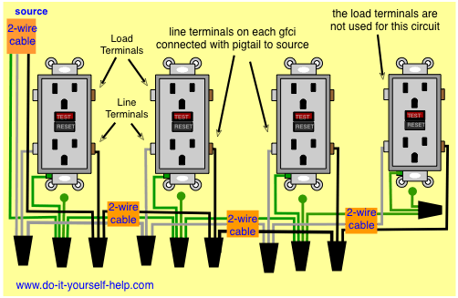
Wiring a gfci combo switch outlet with a light bulb. The neutral and ground wires are spliced together and run to each device in the circuit. Gfci outlet wiring diagram. In this story were adding an outlet to a kitchen that already has gfci protection which has been required for many years. New circuits in kitchens need both arc fault and ground fault circuit interruption afci gfci protection.
Gallery of Kitchen Gfci Wiring Diagram


/cdn.vox-cdn.com/uploads/chorus_image/image/66475077/electrical-upgrades-3-x.0.0.jpg)


/sb10065497e-001-56a27faf3df78cf77276bbbf.jpg)