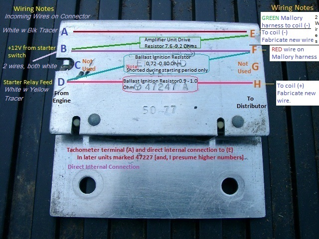
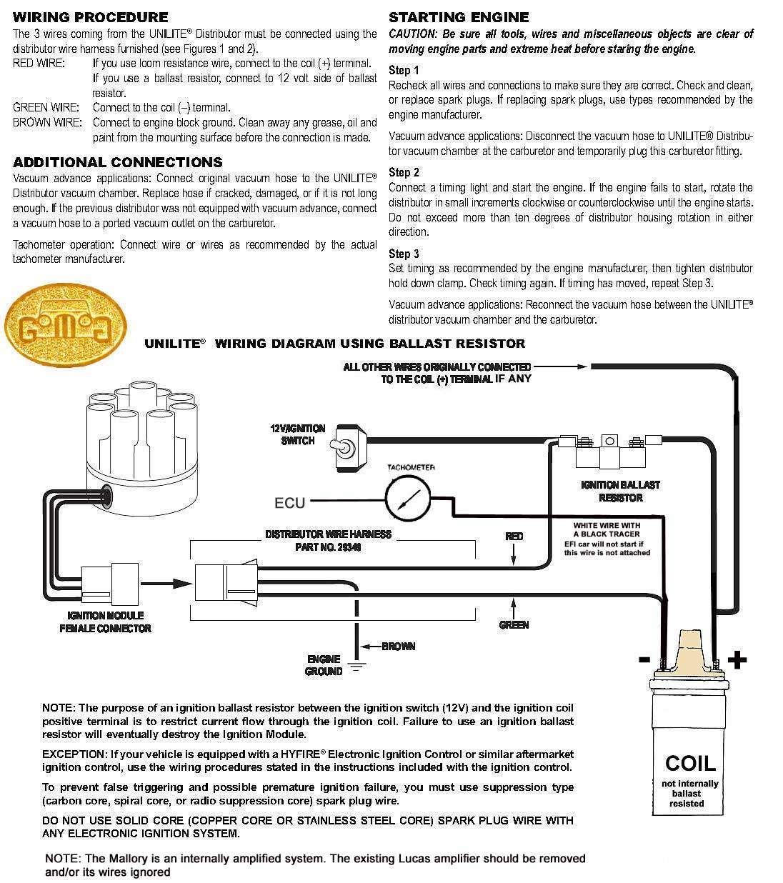
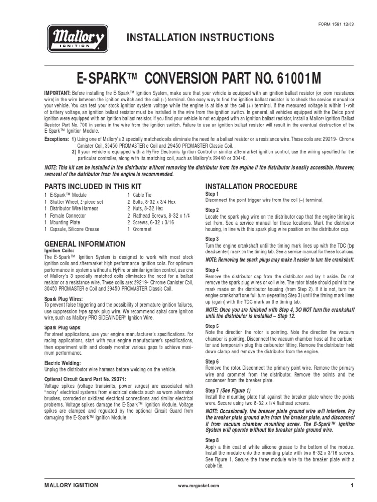
Failure to use an ignition ballast resistor will eventually destroy the ignition module. 29349 ignition ballast resistor brown green red.
4e14a00 Mallory Coil 29440 Wiring Diagram Wiring Library
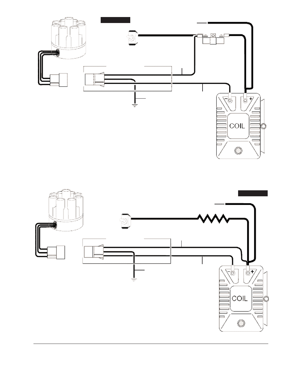
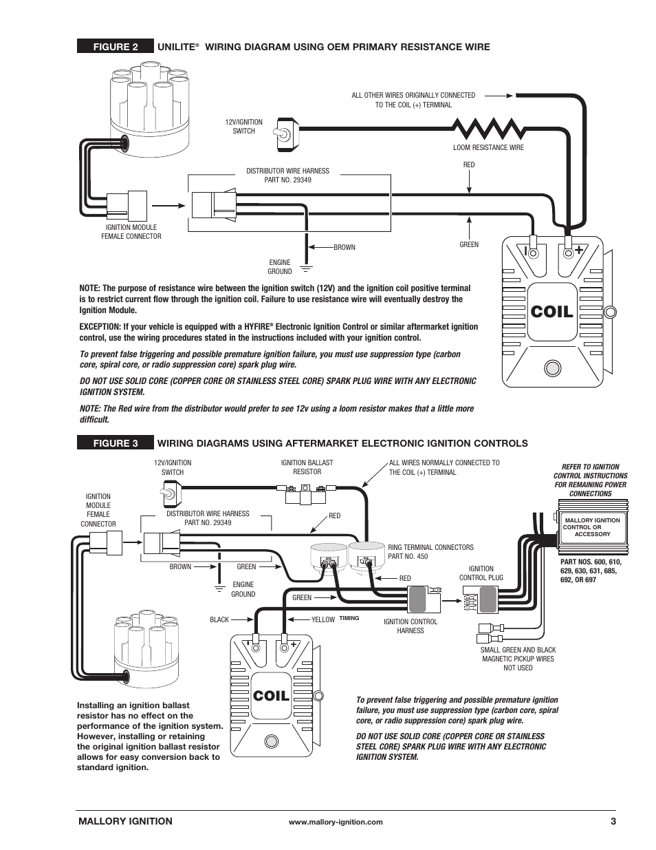
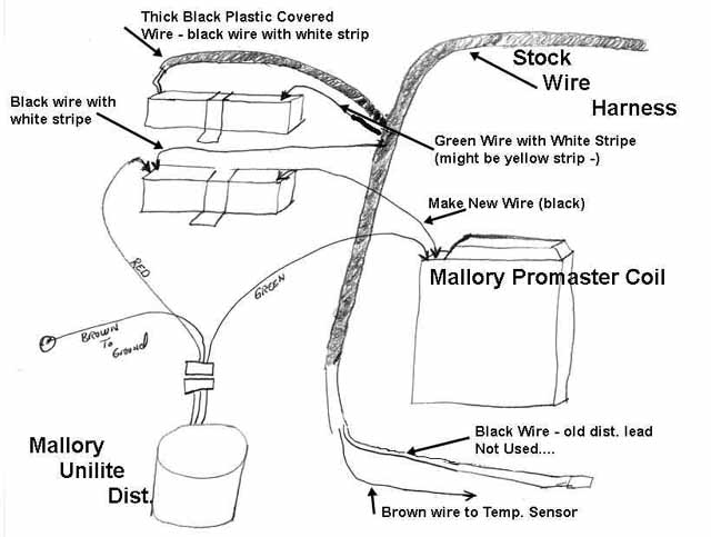
Mallory unilite wiring diagram. If your vehicle has a ballast resistor in line with the coil wiring it is recommended to bypass it. 29349 loom resistance wire brown green red. Figure 1 unilite wiring diagram using ballast resistor coil ignition module female connector engine ground all other wires originally connected to the coil terminal distributor wire harness part no. The purpose of an ignition ballast resistor between the ignition switch 12v and the ignition coil positive terminal is to restrict current flow through the ignition coil. The black wire from the. Routing wires the hyfire wires should be routed away from direct heat sources such as exhaust manifolds and headers and any sharp edges.
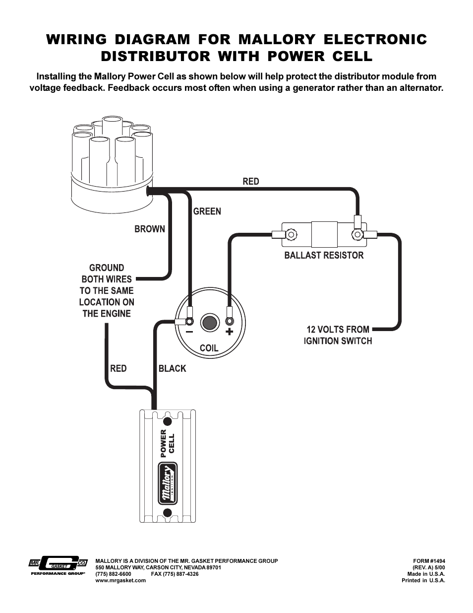
A wiring diagram is a simplified standard pictorial depiction of an electrical circuit. 10 start the three wires of the mallory unilite module through the hole in the nose 14 route the wires from the unilite module to the ignition coil carefully 16 follow a factory shop manual to set the timing for your particular enginewiring diagram for mallory distributer dont worry if your coil doesnt look like this american one or. Mallory ignition wiring diagram free wiring diagram. Installation instructions 3 mallory wwwmallory ignitioncom 915 857 5200 fa 915 857 3344 ballast resistor. To do this the red lead from the voltmeter will go to the green wire on the coil. Collection of mallory ignition wiring diagram.
Name mallory ignition wiring diagram coil mallory ignition unilite distributor user manual best wiring diagram file type source tryit size 303 37 kb dimension 954 x collection of mallory ignition wiring diagram click on the image to enlarge and then save it to your computer by right clicking on the image. Whether you have the mallory unalite or dual point with or without our power amplifier you will find below a wiring diagram to suit and also the original instructions that come with the mallory distributors. Figure 1 unilitewiring diagram using ballast resistor note. Unilite distributor for. It shows the components of the circuit as streamlined forms as well as the power and also signal links between the tools. Wire attaches to the coil.
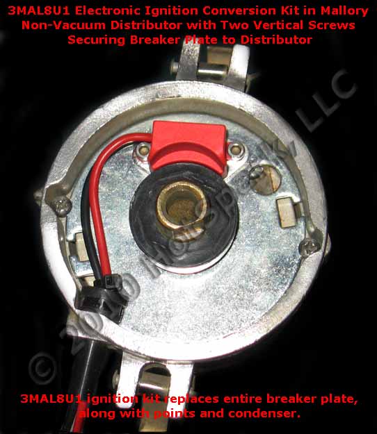
Unilite distributor vacuum chamber and the carburetor. How do i wire my mallory distributor.
Gallery of Mallory Unilite Wiring Diagram