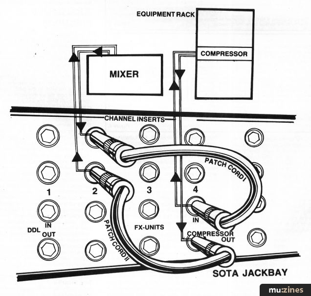
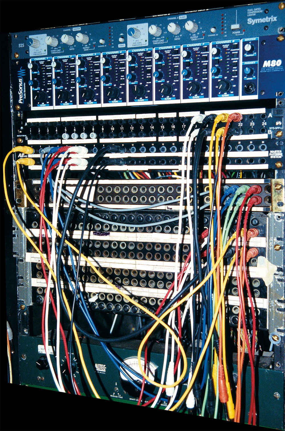
Some manufacturers will also. A patchbay connects all of the inputs and outputs of your outboard gear into a centralized hub.

The Low Down On Analogue Interfacing
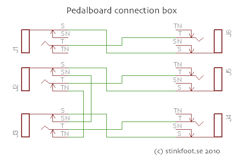
Patchbay wiring diagram. It shows the components of the circuit as simplified shapes and the capacity and signal friends in the midst of the devices. If you have a studio with analog equipment youll benefit from a using a patchbay. Patchbay wiring diagram wiring diagram is a simplified suitable pictorial representation of an electrical circuit. The console mic inputs for each channel which you plug in on the bottom. A patchbay can make your studio much quicker to use but can also be a nightmare to set up so heres advice on which to choose and how to connect it up for the best results. Just be prepared to spend 10 20 of your gear investment for all the cabling youll need.
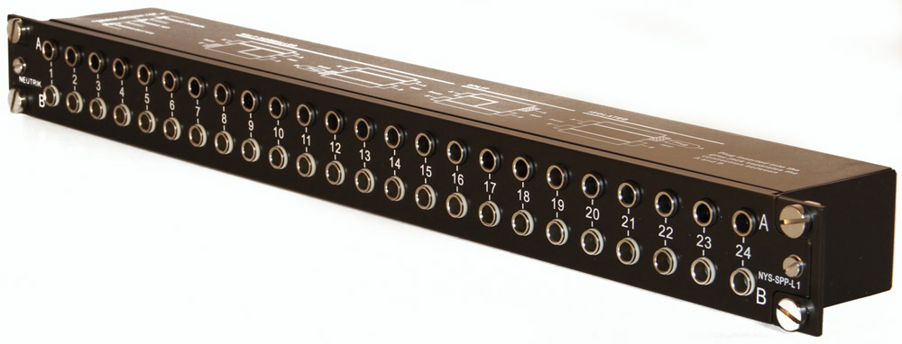
Plus tips on building and fitting racks for your gear. Wiring and diagrams for using an audio patch bay. In my two previous studio installation articles sos september and. The mic tie lines are plugged into the top row in the back of the patchbay which because this patch bay is half normalled automatically get sent to the row below. Typically patchbays have 24 channels per unit. They handle both input and output for each channel which makes 48 points or connections.
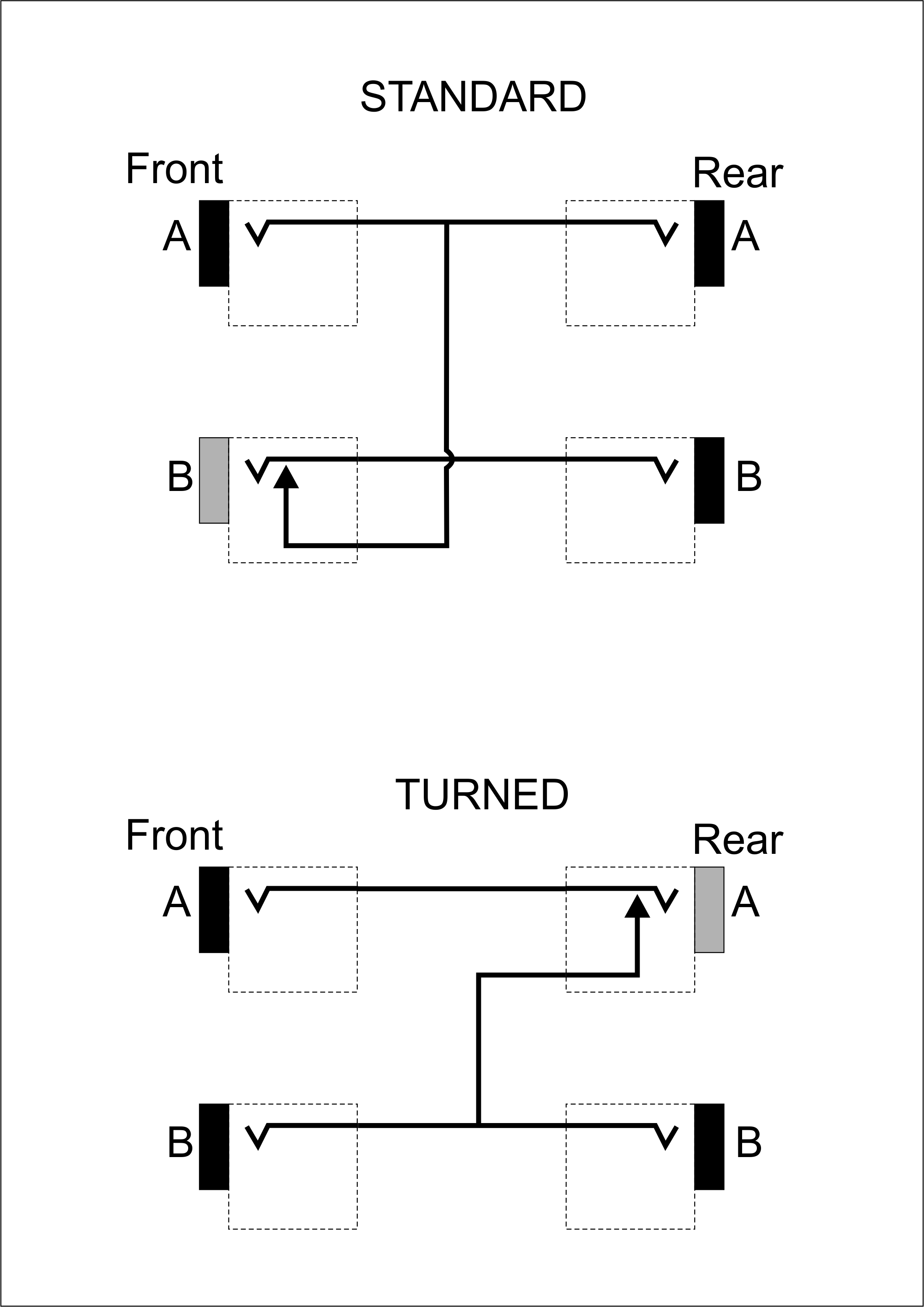
Patchbays include vertical sets of jacks that are mounted in a panel. Installing a patch bay in your home recording studio. This allows you to route one device to the next without needing to go behind a rack full of gear to change one thing. Normal half normal connections normalling refers to a specific wiring pattern within a patchbay that creates a path from one piece of equipment to another without the use of a patchcord. While theres no right or wrong arrangement for connections create a clear wiring diagram.
Gallery of Patchbay Wiring Diagram