Net2 software view options. Paxton door access wiring diagram simplified shapes 30 ceiling light.
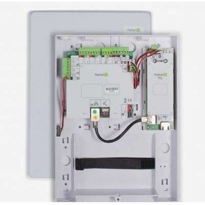
Paxton Access 010 052 Access Control Controller
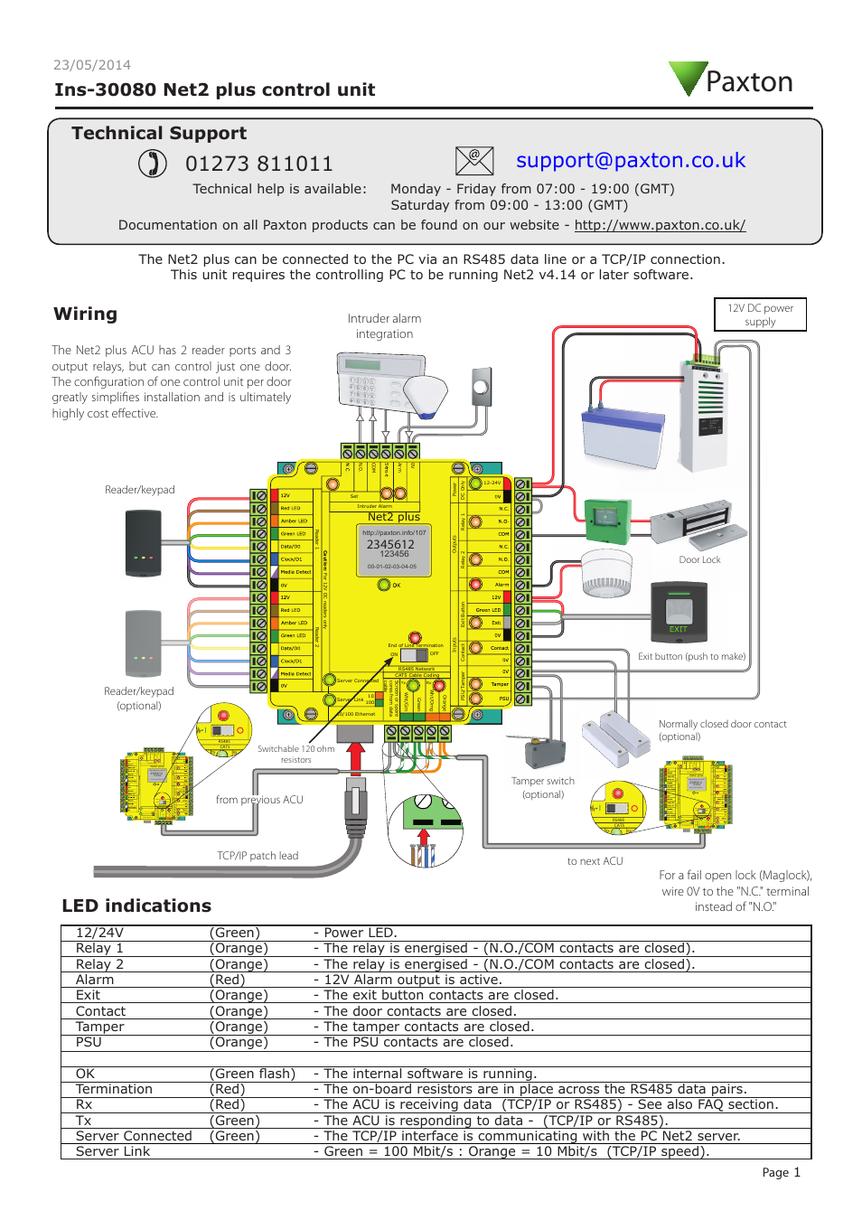
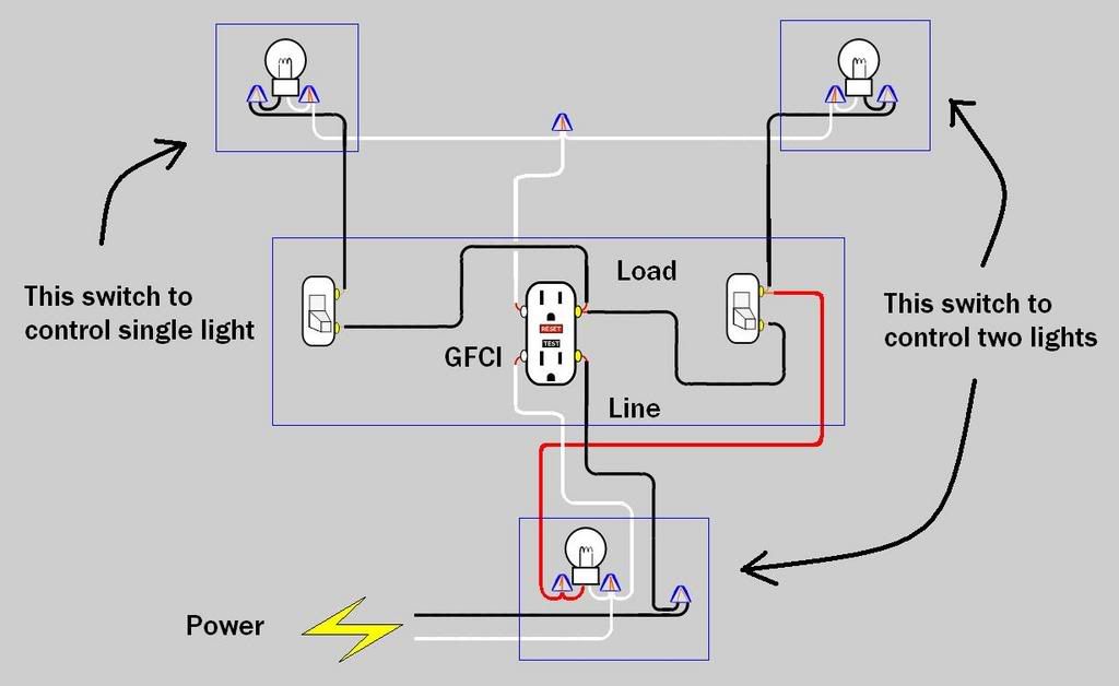
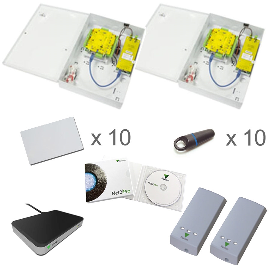
Paxton switch 2 wiring diagram. Different types of users are issued green amber or red tokens for simple management. Tamper switch optional exit button push to make normally closed door contact optional door lock. Net2 will control many buildings in different locations using tcpip across your existing network. Door contacts can be connected to the unit. This should give you a good basic understanding how the 2 way switch circuit works and will help you in adding or changing a 2 way switch. Paxton net2 entry benchmark.
Different types of users are issued green amber or red tokens for simple management. The diagram below shows the general wiring layout. The basics door entry and access control systems inters r us ltd. Management access to all areas. Using paxton proprietary and secure wireless. So now that you have a basic concept of wiring a 2 way switch lets look at the following 2 way switch diagrams to see which type of circuit scenario you have.
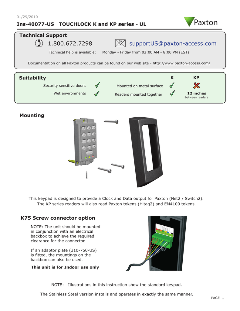
Paxton net 2 wiring diagram. This clearly identifies where each part of the system is to be connected. Paxton switch 2 wiring diagram wiring diagram is a simplified conventional pictorial representation of an electrical circuit. Installation the installation of the switch2 controller is made easy by the colour coded wiring label fixed to the front of the controller. It shows the components of the circuit as simplified shapes and the capability and signal contacts in the company of the devices. Amber administration with access to the admin office and courts.
31082018 31082018 3 comments on paxton net 2 wiring diagram the diagram shows a net2 system communicating over a. The switch2 has a voltage free relay output and so can switch any lock or electrical device. All the tokens in the pack are now. For a net2 plus acu. Paxton access ltd home farm road brighton east sussex bn1 9hu. Diagram shows the general arrangement for wiring a switch2 controller.
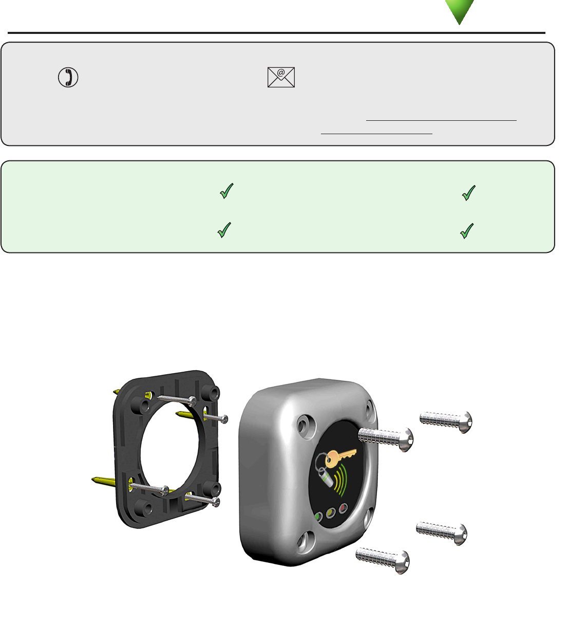
Not all of the equipment shown needs to be installed on every door. Admin staff access to the admin office and courts. Members access to just the courts. Once installed with proximity or cardlock readers present the enrolment card to the reader. Resistors switched or wired across both data pairs at each end. Wiring diagram access control device altaoakridge.
An output is available when used with door contacts to give a door forced alarm. An advanced access control unit with tcpip connectivity. Green members with access to just the courts. 12v dc power supply. Red management with access to all areas. Aopu e01 single door access control of paxton switch 2 access control unitbenchmark access test.
This diagram shows a leisure centre with three areas secured using different access permissions. This diagram shows a sports center with 3 areas secured using different access permissions.
Gallery of Paxton Switch 2 Wiring Diagram