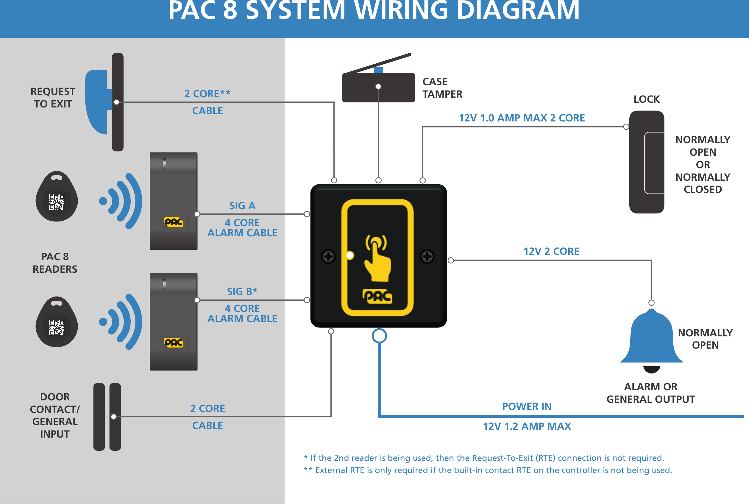
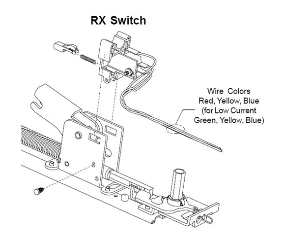
Remove clear protective fi lm from the sensor before use. Connect the 4 wires to the request to exit sensor according to the wiring diagram above.
.jpg)
Push To Exit Button The Ultimate Guide By Kisi
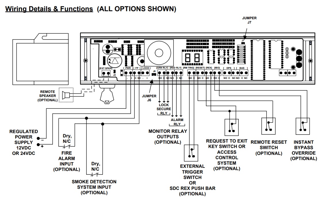
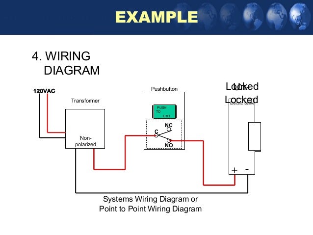
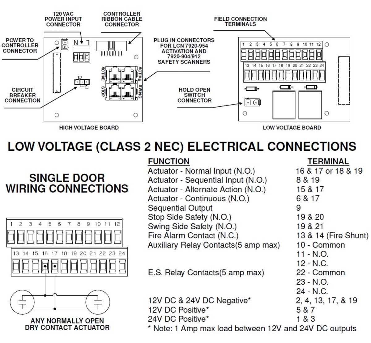
Request to exit wiring diagram. Essex electronics stainless steel vandal resistant request to exit buttons can be used to control an automatic door electric lockstrike magnetic lock or any electrically controlled device. Connect the four wires from the back box to the request to exit sensor according the wiring diagram above. Push to exit button wiring diagram. As illustrated in the 900 4rl wiring diagram later in this article a request to exit switch inside an exit device can also be used to actuate a power operator. Changing the led color jumper placement. Screw the plate into the back box taking care not to crimp the wires.
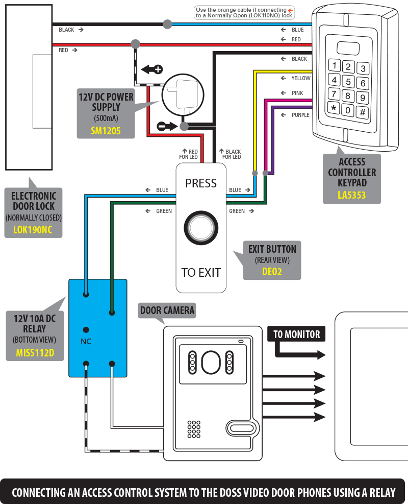
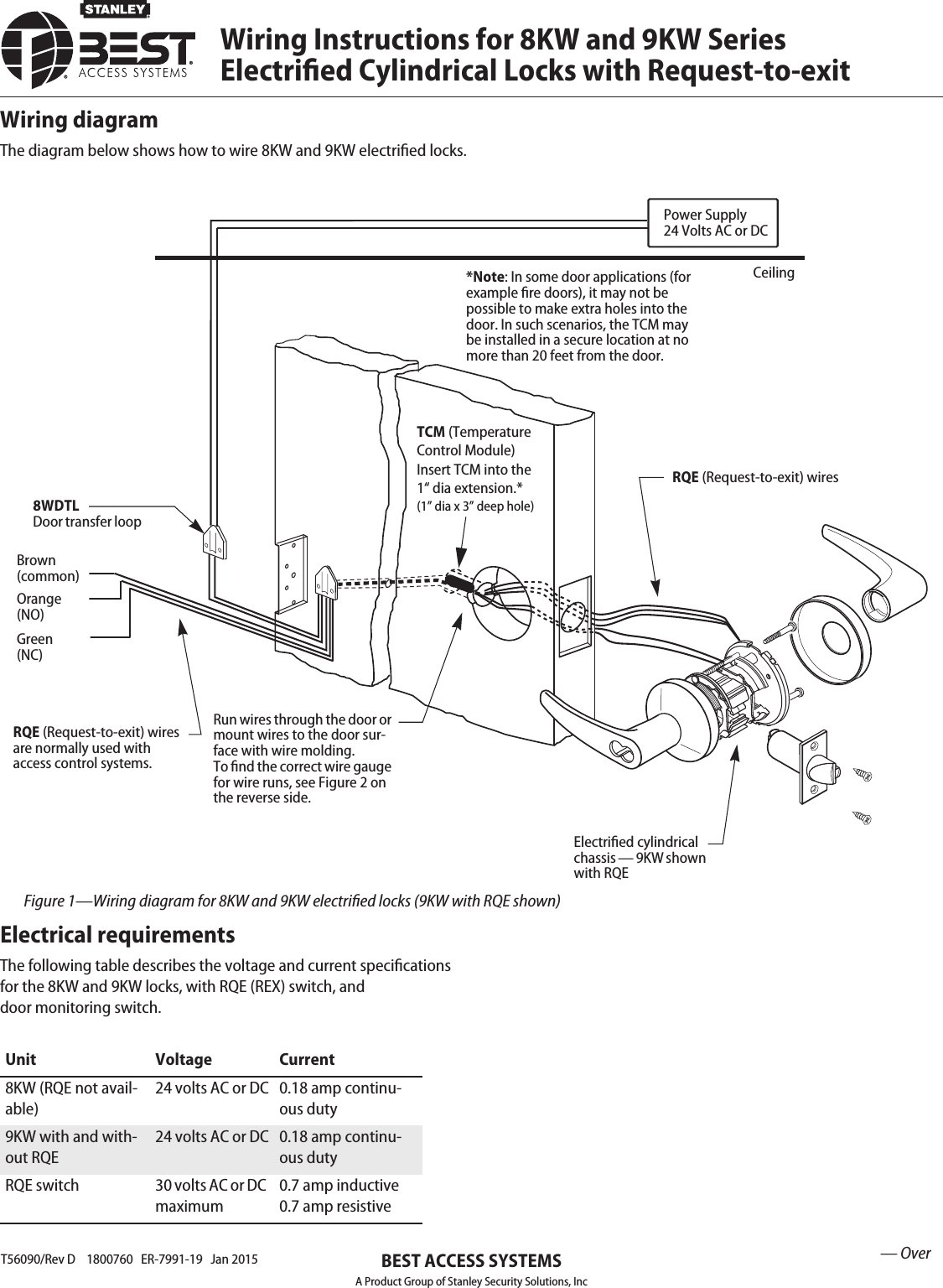
An access control system can also act as an actuator so that persons using the automatic door opener can do so using their access control credential. The schematic diagram of bioxcess door access. Reattach the stainless faceplate to the enclosure taking care not to crimp the wires. Mower wire diagram online wiring diagram the contacts are ul listed with 10 amp capacity. Wiring maglock electromagnetic door lock push button power. Run four wires through the wall to a single gang or slimline back box.
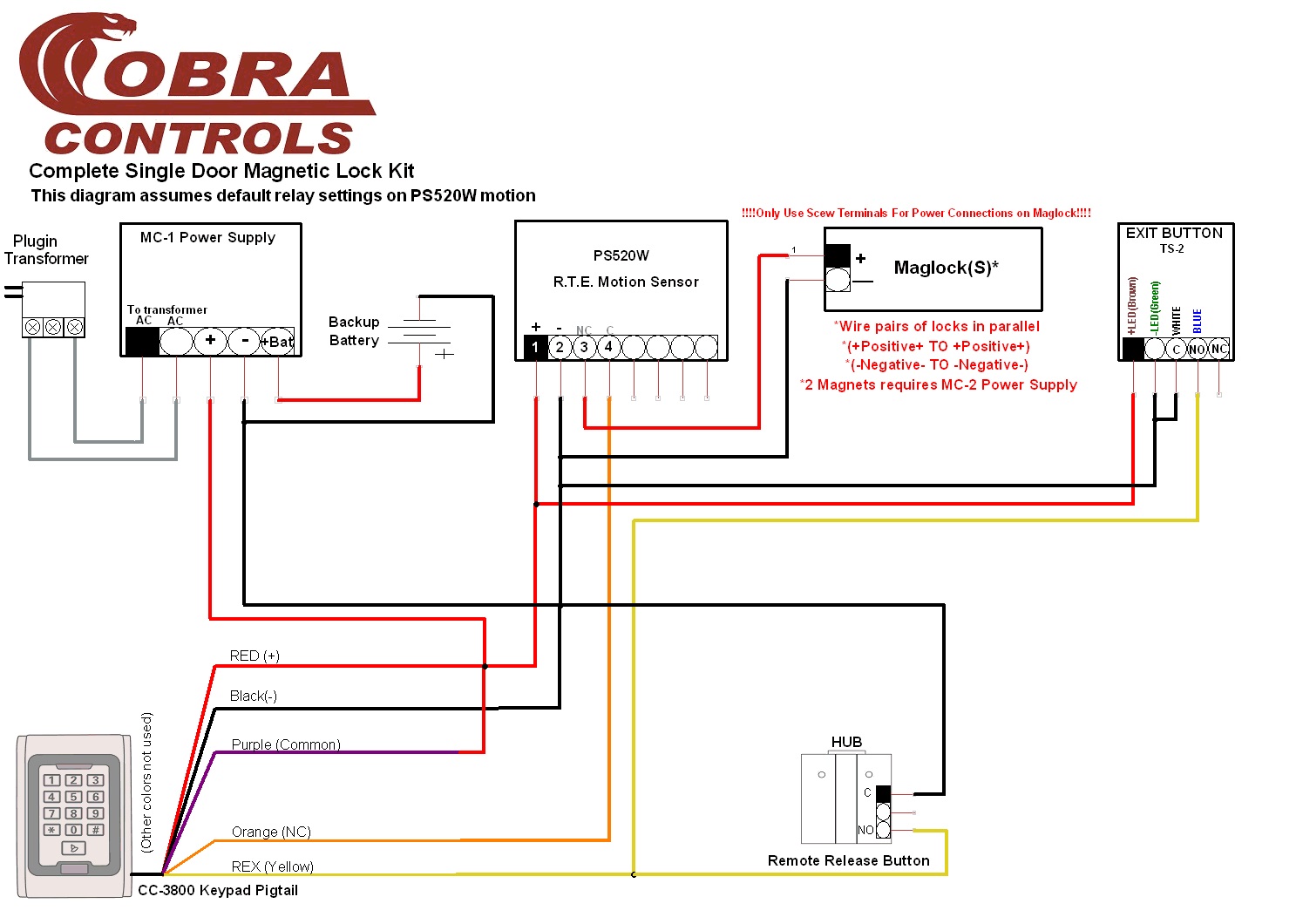
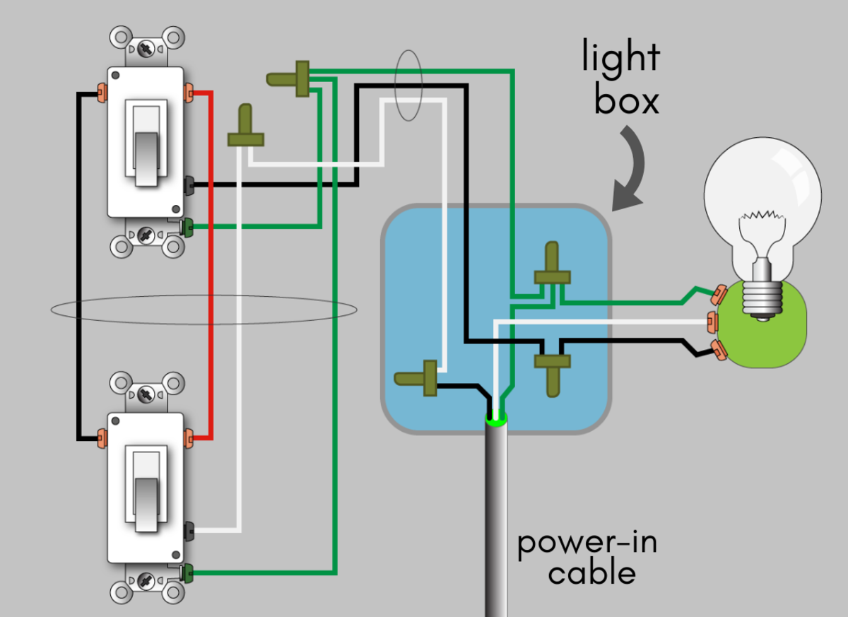
How to wire outdoor reader magnetic lock exit button request to exit pir kit. No touch request to exit sensor seco larm usa inc 3 wiring diagram. Single door controlled egress wiring diagram 01 single door digital entry wiring diagram 10 single door dk 26 with door prop alarm wiring diagram 15 single door dk1 11 xms dt 7 wiring diagram 20 single door dk 26 remote release wiring diagram 14 single door dk 26 unl 24 and dt 7 wiring diagram 18 single door dk 26 using the hard code to toggle lock off and on wiring diagram. Do not connect any device that will exceed 1a at 30vdc.
Gallery of Request To Exit Wiring Diagram
.png)