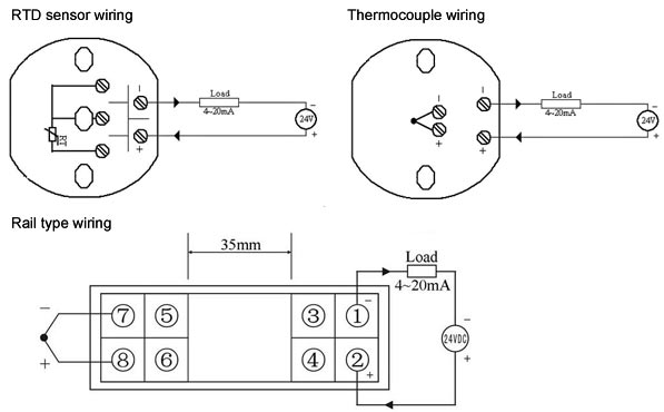
It shows the components of the circuit as streamlined shapes and also the power and also signal links between the gadgets. There are 2 wiring methods for the rtd module and pt100 temperature sensors two wire and three wire connections.

Oc 8009 Rtd Wiring Diagrams Wiring Diagram
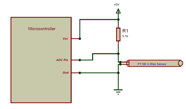
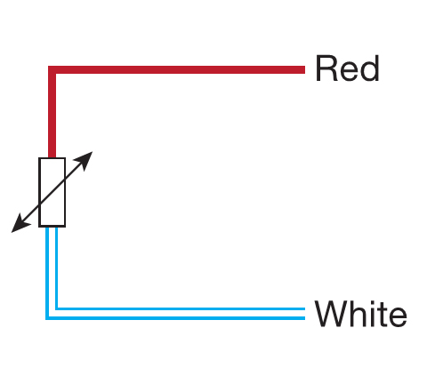
Rtd pt100 wiring diagram. When wiring with two wires first jumper across a1 and b1and a2 and b2 respectively then connect pt100 sensors and to the rtd module according to the following diagram on the left. Rtd pt100 3 wire wiring diagram what is a wiring diagram. The element is usually quite fragile. A1b1 a2b2 and c1c2. Rtd wiring config lady ada rtds are really very simple devices. The most popular rtd is the pt100.
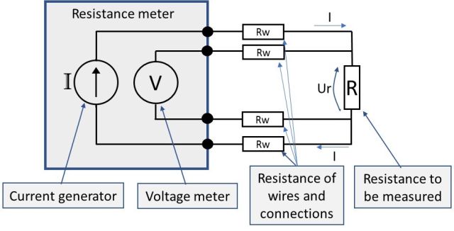
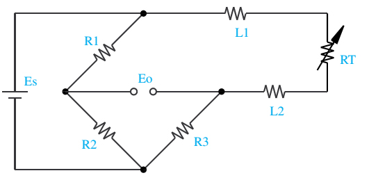
Shown is a 2 wire rtd connected to a typical wheatstone bridge circuit. They have been used for many years to measure temperature in laboratory and industrial processes and have developed a reputation for accuracy repeatability and stability. In this uncompensated circuit lead resistance l1 and l2 add. R1 r2 and r3 are fixed resistors. Just a small strip of platinum that measures 100 ω or 1000 ω exactly at 0 c. Bonded to the pt100pt1000 are 2 3 or 4 wires.
A wiring diagram is a streamlined standard photographic depiction of an electrical circuit. And rt is the rtd. Es is the supply voltage. A wiring diagram is a straightforward visual representation of the physical connections and physical layout of your electrical system or circuit. Eo is the output voltage. It shows how a electrical wires are interconnected which enable it to also show where fixtures and components may be coupled to the system.
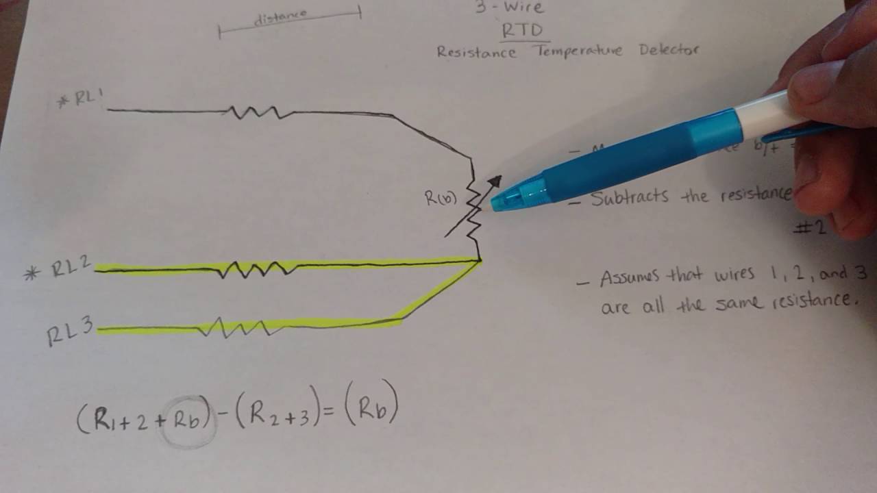
Most rtd elements consist of a length of fine coiled wire wrapped around a ceramic or glass core. Rtd technical data see also. Assortment of rtd pt100 3 wire wiring diagram.
Gallery of Rtd Pt100 Wiring Diagram