This is the june 2011 release revision a of the cfx 750 display cabling guide. How to properly install wiring for a 24v minn kota trolling motor with a circuit breaker.

Trimble Cfx 750 Fm 750 With Ez Pilot Or Ez Steer Adapter Kit
Trimble cfx 750 wiring diagram. After discussing a price with our sales force i decided to go with a cfx 750. Limited warranty terms and conditions product limited warranty trimble navigation limited trimble warrants that this product and its internal components the product shall be free from. Far cheaper if you are moving the cfxt2 and ez steer to move the a full wiring kit for the trimble cfx display and trimble ez steerpolitique de confidentialité filmube. 2 fm 750 display cabling guide contact information trimble navigation limited trimble agriculture division 10355 westmoor drive suite 100 westminster co 80021 usa. Variety of trimble 750 wiring diagram. It applies to version 105 of the cfx 750 display firmware.
Trimble fm 750 headland field pattern. Collection of trimble 750 wiring diagram. I had been considering trading my personal ez guide 500 towards a cfx 750. A wiring diagram is a streamlined standard pictorial representation of an electrical circuit. The 500 provides gps out at times to an insight. The trimble cfx 750 display provides key precision agriculture functionalities including.
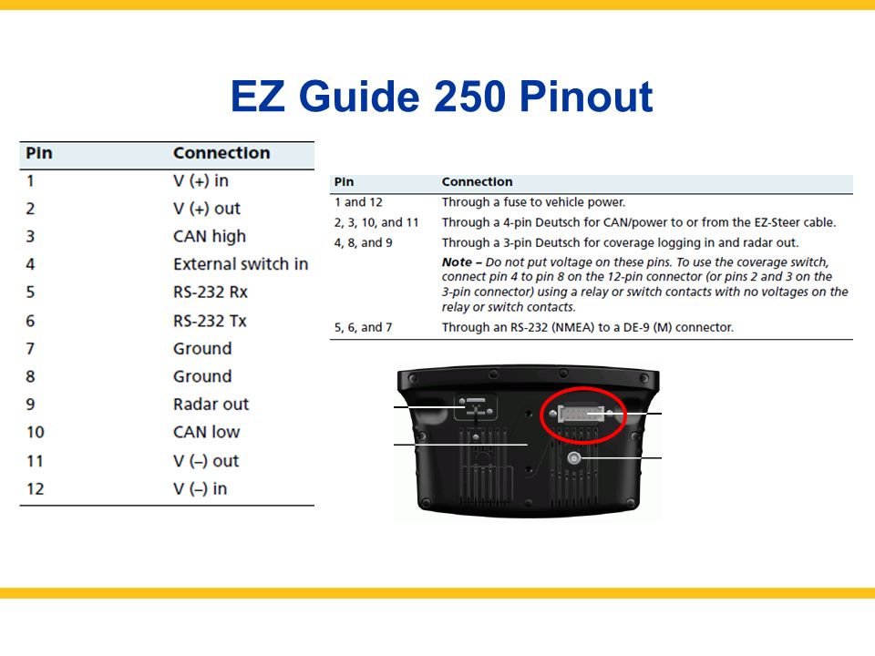
This would be primarily for port a. A wiring diagram is a streamlined traditional pictorial depiction of an electric circuit. The rs232 can power ground and video pins are the same. Trimble cfx 750. I currently use a waas only 500 with trimbles autopilot on a deere 8310. Autopilot fm 750 field iq fieldmanager rawson.
Coverage point line and area mapping. It shows the components of the circuit as streamlined shapes as well as the power and also signal connections in between the gadgets. Trimble navigation limited registered in the united states and in other countries. Posted 2192018 2121 6590451 in reply to 6589800 subject. My used trade in parts would work nicely for the customer. Trimble fm 750 or cfx 750 pinout.
Port a has the pins for the radar signal pin 2 out and the two pins that can be connected together to turn on coverage logging10 11. Steve carmichael recommended for you. It shows the elements of the circuit as simplified forms as well as the power as well as signal connections between the gadgets. Trimble warrants that this trimble product and its internal components the product shall be free from defects in materials and workmanship and will substantially conform to trimbles applicable published specifications for the product for a period of one 1 year starting from. Collection of trimble 750 wiring diagram sample. Manual guidance for a number of field patterns or add hands free guidance with the ez steer ez pilot.
Gallery of Trimble Cfx 750 Wiring Diagram